When arranging a home electrical network, RCDs and circuit breakers cannot adequately protect the system and residents. The best way to prevent an emergency is to ground in a private house. This line is organized according to several schemes, clearly regulated by regulations.
What gives grounding
Particles of electric current (electrons) are directed to positive charges or the contact of grounded devices, if any. If you do not ground the electrical network, electrons begin to accumulate in the cables, damaging the sensitive parts of electrical appliances. When you touch the power loop, a person becomes the point of removal of electrons. This may result in personal injury or death.
In a private or country house, a grounding line must be made in order to:
- eliminating the risks of electric shock;
- automatic power off in the room;
- insulation class 2 equipment;
- equalization of charge potentials;
- protection of power lines, low voltage systems;
- isolation of premises, platforms, recreational areas.
Electrical installation rules call grounding a mandatory part of the electrical network.
Do you need grounding in the country house and in a wooden house
The abundance of household appliances and the legislative regulation of electrical safety explain the need to protect wiring from electrical current. This is especially true for cottages and buildings made of wood.
In a holiday village, most often they build a wooden or frame house. The main communications of the site are pipelines on the surface or the minimum depth, wells, wells. During thunderstorms, these communications can attract lightning.
If a country cottage is not equipped with a lightning rod or grounding, the risks of fires increase at times. In the absence of a fire service nearby, fire spreads rapidly. Owners may lose property or be seriously injured.
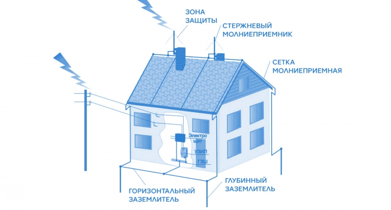
The grounding circuit in the country is not enough - you need a lightning rod.
Grounding systems for a private house
At private construction sites, grounding can be done based on TN-C-S and TT systems.
TN-C-S Application
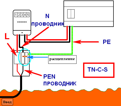
 The main protection device is automatic machines with grounded neutrals. They connect to the ground with a common PEN cable, sharing at the entrance to the building. The danger of the system is the occurrence of phase voltage during the burning of the PEN wire and simultaneous contact of the ground and phase. For this reason, PUEs regulate the construction of the line:
- use of a PEN conductor with mechanical protection;
- standby grounded posts every 100-200 m.
Implementing TN-C-S in rural areas is problematic.
TT system features
The earth wire is fed to the switchboard from an individual grounding circuit. The system is resistant to cable breaks, but does not function without an RCD. The last element eliminates the risks of electric shock.
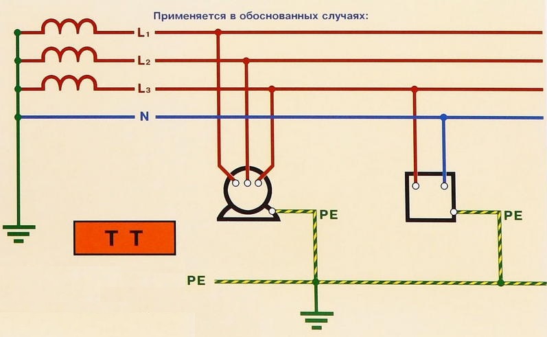
TT - a backup option, which is used in cases of impossibility of organizing TN-C-S.
Grounding device
The home ground loop is a device with internal and external subsystems. Two of its tracks are connected in the switchboard, the rest is on the street. It represents electrodes fastened by plates of metal and dug into the ground. A metal tire extends to the main shield from the structure.The device works on the principle of electric current removal to local soil when a person touches a technique.
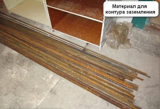
What to do grounding
With your own hands, you can ground from metal rods 16 mm in diameter. One end of the element is sharpened to an acute state, and a flat area is welded on the second.
They also use a metal corner with ledges in the form of shelves with a length of 50 mm, which are quickly hammered by a sledgehammer into soft soil.
Pipes with a tapered or cone-welded edge are also suitable for arranging protection. You will need to make holes with an indent of 50 cm from the edge, so that the system functions in conditions of dry soil. To restore work, a solution of salt with water is poured into the elements. The lack of technology is the need to dig or drill a well.
Grounding cannot be done from the reinforcement - the red-hot layer changes the direction of the current and quickly splits in the soil.
Modular pin grounding
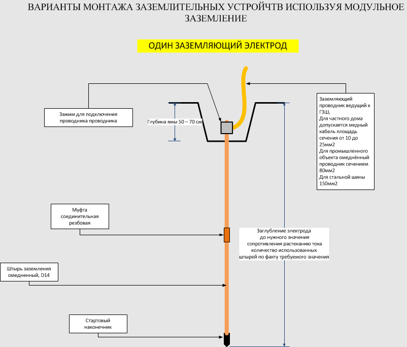 The design is a steel pin 1.5 m long with a copper coating. The ready-made kit of modular pin grounding for home and garden is connected by couplings. The vertical and horizontal elements are fastened with a brass clamp.
Assembly and installation are carried out sequentially:
- The pin is treated with an anti-corrosion agent.
- A nozzle-tip is installed on the upper part for the convenience of working with a vibratory hammer.
- A pointed tip is put on the second end of the rod and coated with an anti-corrosion agent.
- A flat pad is worn on top of the pin.
- Digging a hole in the ground.
- The grounding kit in the assembly is placed in a pit and screwed to maximum depth.
- With a vibratory hammer, the structure is immersed in the soil, leaving 20 cm to attach another rod.
Ready-made modular device occupies a small area, does not require welding. All parts of the structure are manufactured in the factory, so they are assembled without effort.
Ferrous metal circuit
 A grounding electrode is any rod of black metal - steel corners, pipes, smooth reinforcement, I-beams. The optimum metal cross section for operation over 20-30 years is not less than 1.5 cm2.
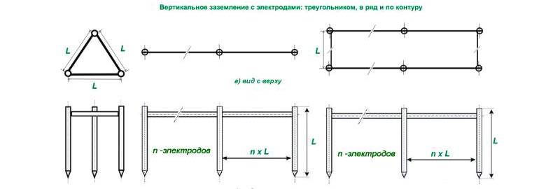
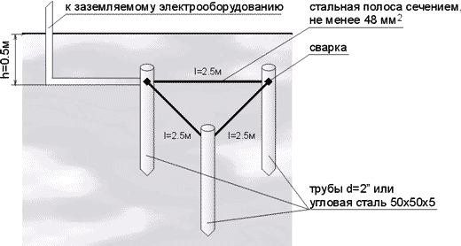
A popular option by which a protective circuit can be made is in the form of a triangle, where the electrodes are vertices. The pins are connected by strips of metal, a similar element extends to the switchboard. Depending on the soil resistance, the rods are installed at a distance of 1.2 - 3 m.
IEC 60364.5.54 notes that in the conditions of sandstones, alkaline soils with low GW, it is possible to use galvanized black metal pins.
Plugging Depth
Clogging of metal rods to a depth is allowed:
- from 80 to 100 cm, but not less than 60 cm below the level of soil freezing;
- from 100 to 200 cm in the presence of plastic, moving soils on the site;
- 1/3 protrusion in moist soils.
A frozen or dry topsoil increases soil resistance by 10 times.
What can not be done
To safely ground the site and the house, you should pay attention to the prohibitions of the PUE. According to the document you can’t:
- use metal with corrosion - there are risks of short circuits;
- use the armature as a ground electrode and conductor - the current destroys the red-hot layer and the rod quickly rusts;
- to lay a circuit at a distance from a residential building of not more than 1 m - the system will be ineffective;
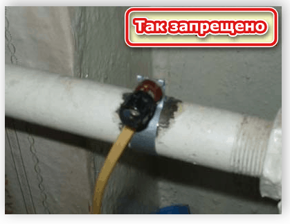
- use as a contour of the heating pipe or water supply - the system will not be complete;
- combine the PE conductor with a working zero behind the separation section - the circuit breaker will start to operate constantly;
- set the jumper to zero and the PE conductor of the outlet - when the zero is broken, a phase will be applied to the housing of the household appliances.
Detailed recommendations are given in the Electrical Installation Rules.
How to do it right

For the correct installation in the protective earthing area and entering it into the house, it is worth choosing the material and shape of the grounding conductors.
The design is made of steel or copper metal elements:
- vertical rods from 16 mm;
- horizontal rods from 10 mm;
- steel products from 4 mm thick;
- steel pipes with a diameter of 32 mm.
The shape of the ground electrode can be in the form of an equilateral triangle with pins-vertices. The second option is a line with 3 elements located exactly. The third method is a circuit in which the rods become clogged with a step of 1 m and are connected by metal bonds.
A step of 1 m is suitable for buildings with a quadrature of 100 m2.
Procedure
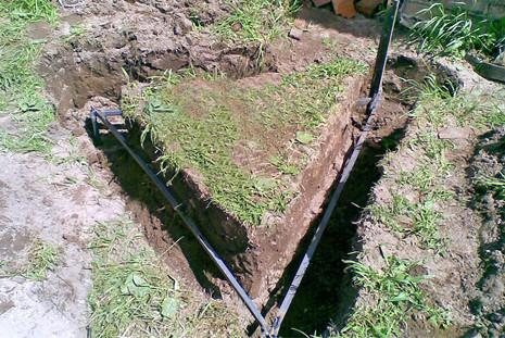
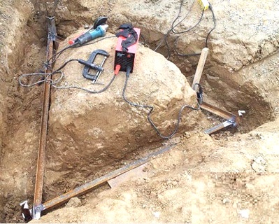
Grounding installation should be considered as an example of a triangle. They work as follows:
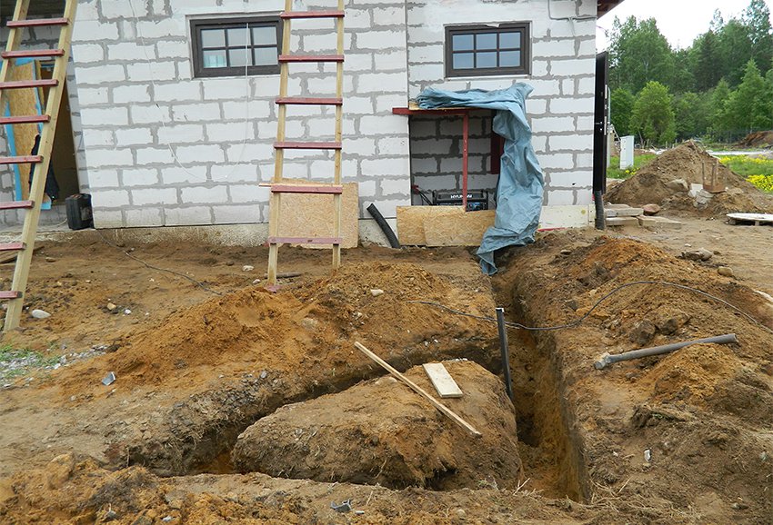
- Make a marking in the form of triangles indented from the beginning of the blind area to the installation site at least 150 cm.
- Dig trenches in the form of a triangle. The size of the sides is 300 cm, the depth of the grooves is 70 cm, the width is from 50 to 60 cm.
- The top closer to the structure is connected by a trench 50 cm in depth.
- At the tips of the peaks, elements (a round pin or a corner) of 3 m in length are clogged.
- The earthing switch is lowered below the soil level by 50-60 cm. It rises 10 cm above the bottom surface.
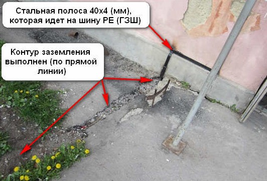
- Metal bonds are welded to the visible parts of the elements - strips 40x4 mm.
- The triangle is brought to the house using metal strips or round conductors with a cross section of 10 to 16 mm2 and welded.
- Slag is removed from the connection points, the structure is coated with an anti-corrosion agent.
- Check the resistance (should be up to 4 ohms) and fill the grooves with soil without major impurities. Each layer is tamped.
- At the entrance to the house, a bolt with an insulated copper conductor with a cross section of 4 mm2 is welded to the strip.
- Throw grounding into the shield. Connection is made to a special unit covered with a grease.
- Earth is connected to each house-divorced line.
According to the PUE, it is impossible to separate the "earth" with one conductor - only in a common cable.
Entering the ground loop in the house
To enter the circuit into the house, it is worth using a steel strip 24x4 mm, a copper wire with a cross section of 10 mm2, an aluminum wire with a cross section of 16 mm2:
- Conductors with insulation. A bolt should be welded to the circuit, and a sleeve with a round non-contact area should be put on the end of the conductor. Next, assemble the device by screwing the nut on the bolt, the washer on it, then the cable, washer and tighten everything with the nut.
- Steel strip. A bus or conductor is put into the room. To ensure the accuracy of execution, conduct a copper bus with small dimensions.
- Transition from a metal busbar to a copper wire. Two bolts are welded onto the bus with a distance of 5-10 cm. A conductor is wrapped around the elements, the bolts are pressed with washers.
The latter method is more convenient for wiring through the wall.
Why you can not do separate grounding
The installation of separate earths will not ensure the efficient operation of household appliances. Electric current can cause damage to humans. If the house has 2 or more sockets with separate earthing, the equipment may fail. The reason is the dependence of the resistance of the contours on the state of the soil in a separate area. A potential difference may appear between the structures, which will damage the equipment or cause electric injury.
Which system to choose
In the private sector, only two schemes are used today - TN-C-S and TT. Most often, a two-wire conductor for 220 V or four-wire - for 380 V is brought to the structure.
Grounding device TN-C-S
The TN-C-S grounding circuit will provide high-quality protection only in the presence of a differential machine and an RCD. Connect all systems based on current conductors (water supply, foundation reinforcement, sewage, heating) to the earth bus with separate wires:
- The choice of tires for wiring PEN cable. You will need a “ground” (PE) with a metal base, a neutral (N) with a dielectric base and a 4-point splitter.
- Connection of the metal bus to the metal casing of the shield to form contacts. The paint on the attachment points is completely removed.
- Mounting the zero bus on a din rail.
- Checking the location of the tires - they do not intersect.
- Institution of the PEN conductor on the release.
- Connection to a grounding release.
- Installing a jumper on the earth bus from one socket using a copper wire with a cross section of 10 mm2.
- Installation of a jumper from a free slot to a neutral or neutral bus - a similar copper wire is used.
Consumers are connected according to the principle of stretching the phase from the lead-in wire, zero from the neutral bus, earth from the PE bus.
TT grounding
The TN-C system in older homes can be converted to TT. The phase cable from the pole is used as the phase, and the protective cable is fixed to the zero bus and remains neutral. The conductor from the finished circuit is immediately displayed on the ground bus.
The disadvantage of the TT system is to protect exclusively equipment thrown on the ground wire. The remaining devices connected using the two-wire method will be live. In the case of grounding the enclosures with additional conductors, the voltage during surges remains zero, and the machine can break the phase.
Why, in the presence of grounding, an RCD is needed
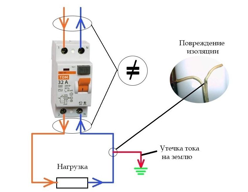
The residual current device is necessary to equalize the phase and zero current. If there is a risk of leakage, the RCD will de-energize the line and even when it touches the device body, the electricity will go into the ground.
The circuit without grounding and RCD
If the house does not have grounding, the installation of the protective device is carried out in two ways.
At the entrance.The appliance is the only means of protection for all home wiring. Voltage will be supplied through the input cable to the switchboard, then to the bipolar circuit breaker, and then to the RCD. After that, you can connect the machines to the outgoing lines.
The scheme practically does not require financial costs, provides a compact arrangement of all devices. Its minus is the operation of the device in the current leakage mode and the blackout of the entire building.
At the entrance and branch lines.The lead-in device is mounted at the entrance, and auxiliary devices are near the automatic machines of the withdrawal lines. The number of RCDs is determined by the branching of the electrical network. It is allowed to connect boilers, washing machines, electric stoves and dishwashers to the protection. According to this principle, it is convenient to connect a garage, cellar or utility buildings.
At the moment of current leakage, a specific device is triggered, one type of equipment stops, the rest work in standard mode. The disadvantage of the system is that grounding is installed for a long time in a dimensional shield, which is not cheap.
RCD in a system without a protective conductor TN-C
The system includes a three-phase (4 pcs.) Or single-phase (2 pcs.) Wire. The first consists of 3 phases and one zero, the second - from 2 phases and one zero. In cases of damage to the insulation layer, the apparatus does not immediately respond, since the leakage current does not appear.
When touching a damaged technique, part of the voltage will enter the human body. Only then will the RCD start to work. In 1/10 second, much can happen - from unpleasant tingling to electric burns.
Circuit with protective conductor (TN-S and TN-C-S) and RCD
When equipment connected through an RCD with a ground loop comes into contact, a current leak immediately occurs. It occurs when a phase closes on the equipment body. The machine is activated, breaks the connection, the current is diverted to the ground.
Gas boiler and RCD
Grounding the gas boiler should be mandatory, at the same time as installing the RCD. The need for work is due to the formation of surface tension on the boiler body during operation.Grounding in this case will prevent equipment failure, eliminate the risk of ignition from static electricity. The arrangement of the line will also provide additional fire protection, since the gas is explosive.
Grounding the power grid is a universal way to protect human life, prevent breakdowns of insulation, breakdowns of household appliances. Power lines without grounding are fire hazardous, but it is necessary to install a protective system in accordance with the neutral, phase, and earth connection diagrams.