Input is the part of the pipeline that connects the external water supply to the water metering unit in the house or in the central heating unit. Knowledge of the rules for arranging the introductory section is necessary for the functional integration of elements of the water supply network inside and outside the building.
Device and scheme of water mains
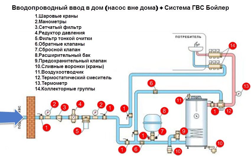
The inlet section connects the external water supply network from the connection point to the water meter unit or the overlapping element. The complex also includes the sealing of the passage of pipes into the house.
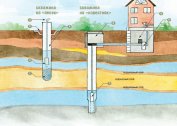
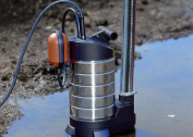
There are two types of introducing a water supply main into a building: from a central network or from a local water source. The decentralized method is applied when water supply systems are located far from buildings. Connection is made from a well or a well. In this way, private houses are usually fed, they are equipped with a single input.
In high-rise buildings, each connection to the water supply line accounts for 400 or fewer apartments. The number of introductory sections depends on the mode of providing moisture to consumers:
| Number of entries | Installation option |
| One | In buildings inside which there are dead ends and less than 12 fire hydrants. |
| Two and more | Inside the buildings there are more than 16 floors, as well as in buildings equipped with a zone water supply system and where more than a dozen fire hydrants are provided. |
The total number of entries is determined by the selected water supply scheme. In residential and public buildings of standard construction, usually one opening node.
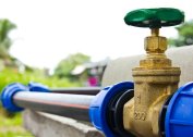
At the junction of the input and the external part of the water supply network, a well tank with a diameter of at least 70 cm is equipped to accommodate shut-off valves. This can be a valve or a valve, allowing at any time to block the water flow.
When installing two or more inputs, they are connected to different sections of the external annular highway, mounting a dividing valve on it. If pressure equipment is additionally installed that increases the pressure inside the water supply network, the inlets are arranged in front of the pumps. At the same time, locking elements are mounted on the unit. They will provide moisture to all pumping equipment. Inputs are not connected if each of them is equipped with an independent pressure station.
If the house is connected to a centralized network, the installation of a water meter is mandatory.
Connection of water inlets
 The introductory section is connected to an external water supply network using one of the following methods:
- directly to tees, crosses or plugged holes left during the construction of the city highway;
- connecting the pipe to the line by welding or by inserting a tee;
- through the saddle.
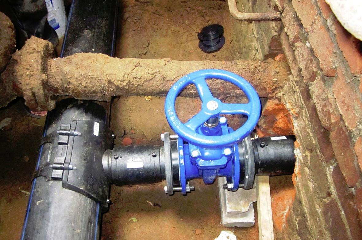
In the latter case, a cast-iron shaped part is used, fixing it to the water supply with a clamp on a rubber gasket. The nurse-gun is used when there is no way to block the external water supply. Locking fittings are fixed on it - a through valve or valve - by means of a threaded or flange connection. To drill holes in the pipe, a drilling device is attached to the locking element.
The valve or gate valve is also installed at the point of connection of the input with a cross section of more than 50 mm to the external water system. Introductory nodes are equipped with stops in sections of turns on a vertical or horizontal plane.
When mounting several inlets with measuring instruments connected by pipe sections on the internal highway, it is required to provide for the installation of check valves
Pipe materials and size
For the arrangement of bushings with a cross section of 50 mm or more, mainly cast-iron pipes are chosen, with a diameter of less - steel, galvanized or polymer pipelines. Steel products without zinc coating with bitumen insulation against rust are used at a pressure in the line of more than 1 MPa and a cross section of bushings of more than 50 mm.
When selecting pipe segments according to the size of the section, they are repelled from two criteria: the speed of the water flow, as well as the total length of the water main. The first indicator, as a rule, is standard: water moves at a speed of approximately two meters per second. The second varies depending on the area of the building and the remoteness of plumbing fixtures. For example, with an estimated length of water supply of less than ten meters, pipe sections with a cross section of 20 mm, from 10 to 30 m - 25 mm and more than 30 m - 32 mm, are quite enough.
Building regulations
The water supply input node to the building is equipped under a non-residential premises, for example, under a staircase, since a station of two pumps can be located next to it: a working one and a spare one. The presence of pumping equipment under residential premises is prohibited by the Building Code and Rules 2.04.01-85.
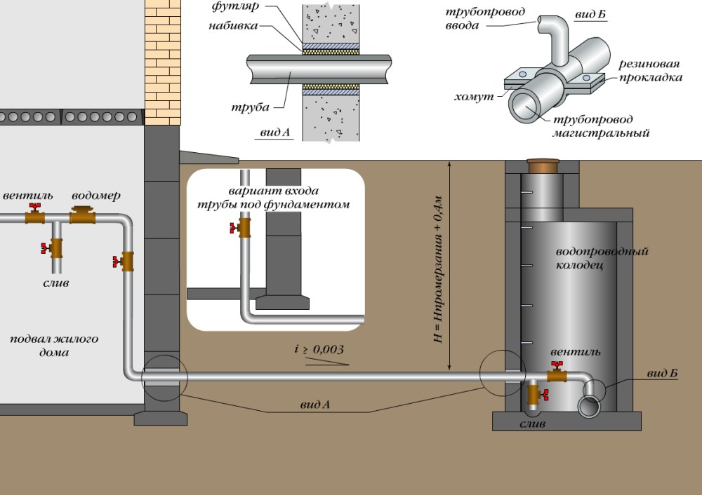
Laying the inlet pipeline is carried out at a minimum distance at an angle of 90 degrees to the wall of the house and with a slope of 0.005 to the city highway. This will drain excess moisture.
The introductory section at the point of passage through the wall or the foundation of the structure must be protected from mechanical damage. To do this, pipe segments in dry soils are laid in cases made of steel sleeves with a ring gap covered with tarred fiber and mashed clay, and on the outside with cement mortar for sealing. In the soils saturated with moisture, ribbed tubes are used to equip the inlets passing through the walls and foundation foundations, and with the proximity of subsoil sources, glands are used or sealed with cement, concrete mix.
The size of the entry hole in the wall of the foundation foundation or basement of the building should be 40 mm larger than the section of the input pipe.
The minimum distances in the horizontal direction from the inlet pipes to other underground utilities are established by building codes:
- to the heating main - 1.5 m;
- to the sewer line with an input cross section of up to 20 cm - 1.5 m, more than 20 cm - 3 m;
- to gas pipelines of low pressure - 1 m, medium - 1.5 m;
- to electric cables and telephone wires - 0.75–1.0 m.
At the intersection with the sewage, the water supply network is laid 40 cm higher. The inlet section is ideally also located above the sewer pipes. If the input of water supply can be arranged only below the output of wastewater, the distance criteria listed above should be increased by the difference in the depth indicators of the pipeline laying. In this case, steel pipes must be used, placed in a case with a take-off in both directions up to a meter.
The depth of the water main entrance depends on how the external water supply pipeline passes. It is important that the lead-in areas are below the freezing level of the soil. The minimum depth indicator for laying is a meter, but only if the temperature of the earth at this level is above zero. Be sure to note that to ensure free drainage from the system, the input is installed with a slope of 0.005 towards the external water supply network.
The arrangement of the introductory section should be provided even before the construction of the building. If you are having difficulty creating the circuit for this unit yourself, you should contact the design office.