The first electricity meters appeared in the 19th century. This can be explained by mass studies of electromagnetism, which were carried out by scientists. Today, electricity meters are divided into several types and are installed in all rooms where people consume electricity. Its main task is to stabilize and, if used correctly, to minimize utility bills.
Classification of electricity meters
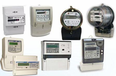
All meters for electricity are classified by type depending on the type of connection, design features and measured values. Devices are divided into directly connected to the power line and devices that are connected to the electrical circuit using measuring transformers.
Depending on the design features, electric meters are divided into the following types:
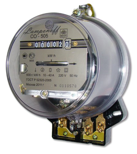
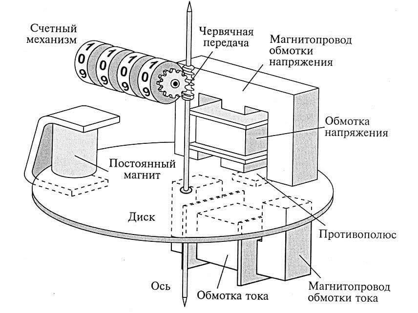
- Electromechanical or induction. The principle of operation of the electric meter is as follows: the moving part made of a conductive material is directly affected by the magnetic field, which is formed by stationary conductive coils. The moving part is the disk, and the coils produce currents, driving this disk. The amount of resource consumed is directly proportional to the number of revolutions of this disk.
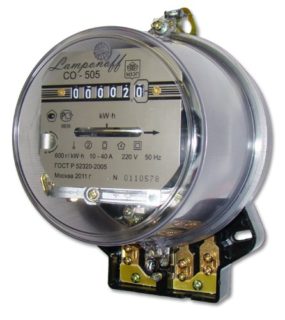 Single tariff induction counter
 - Static or electronic metering device. The principle of operation of the electronic energy meter is as follows: electronic, they are solid-state, parts are susceptible to voltage and alternating current, which creates pulses at the output, the number of which is equal to the volume of the measured energy resource. Such an electric meter device allows you to measure active energy by converting voltage and analog current signals to counting pulses.
- Hybrid types of metering devices are quite rare. A feature of the device of the electric meter is the similarity of the design of mechanical and electronic devices.
Electric meters are classified into several types according to measured values and the number of tariffs. In the first case, metering devices are single-phase and three-phase, in the second - single and two-tariff.
The device and principle of operation of the electric meter
In order to real-time and continuously record the active energy consumption of alternating current, it is necessary to install single-phase or three-phase induction meters. If it is important to take into account direct current, which is widespread on the railway and all types of electric vehicles, electrodynamic meters are mounted.
Induction electric meters are equipped with a disk made of aluminum; when the resource is consumed, this moving element rotates due to the vortex flows created by the induction coils. In this case, there are two different forces - the magnetic field of the induction coils and the magnetic field of eddy currents. The resulting currents flow in a parallel load circuit. Each coil is equipped with a core that is magnetized by alternating current. The effect of continuous alternating current leads to the fact that the poles of electromagnets are constantly changing. This leads to the passage between them of a magnetic field. It is it that pulls the aluminum disk behind it, forming a rotation.
The speed of rotation of the disk is directly proportional to the magnitude of the currents in both coils.In the production of electric meters, simple connecting techniques from mechanics are used, due to which the rotating disk is connected with the digital readings on the panel.
Accounting for the consumed resource is based on the forward voltage and current voltage. All data is fed to the indicator; in advanced models, data is stored in the device memory.
 In recent years, people have increasingly preferred electronic two-tariff structures. Continuously increasing demand is explained by the following list of advantages:
- Devices more accurately read information, which reduces the cost of utility bills.
- Compared to mechanical electric meters, they have a compact size and a more attractive appearance.
- Automatically switch to day and night tariffs, human participation is not required. Even at the production stage, the device is programmed for two time intervals - from 07:00 to 23:00 and from 23:00 to 07:00.
- Advanced models need to be checked once for 5-16 years. Such verification is required for the correct accounting and accrual of funds. Verification should be done by the energy supply company.
The first check of the device’s performance is carried out in the factory, the date must be indicated in the accompanying documentation.
Among the disadvantages of two-tariff metering devices, high cost and their unreliability are distinguished in comparison with mechanical counterparts. As practice shows, electronic models often fail.
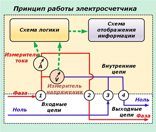
Schematic diagram of the electric meter
The scheme of operation of all types of electrical appliances has no fundamental differences, they are all similar.
To measure power, several simple sensors are involved:
- Voltage sensors, the operation of which is based on a known divider circuit.
- Current sensors based on an ordinary shunt through which the phase of the electric main passes.
The signal that is detected by these sensors is small, so it needs to be amplified using electronic amplifiers. Then, analog-digital processing is carried out to transform the signals and multiply them.
The following steps are filtering the digitized signal and displaying data on the display:
- integration;
- indication;
- transfer calculations;
- conversion.
In this scheme, the used input sensors are not able to provide measurements of a high accuracy class of vectors, and therefore, the calculation of power.
If high measurement accuracy is required, the circuit is additionally equipped with special measuring transformers.
If in comparison we consider the basic scheme of operation of a single-phase electronic meter, in it the VT is additionally connected to zero and phase, and the CT is an integral component of the phase wire break. Since the signals come from two transformers, additional signal amplification is not required. All further transformations are performed by the microcontroller, it controls the display, random access memory and electronic relay. The output signal through RAM can be further transmitted to the information channel.