Due to the use in everyday life of a large number of electrical appliances (microwaves, electric kettles, computers, etc.), it is often necessary to adjust their capacities. To do this, use a voltage regulator on the thyristor. It has a simple design, so it is not difficult to assemble it yourself.
Design Nuances
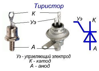
A thyristor is a controlled semiconductor. If necessary, it can very quickly conduct current in the desired direction. The device differs from the usual diodes in that it has the ability to control the moment of voltage supply.
The regulator consists of three components:
- cathode - a conductor connected to the negative pole of the power source;
- anode - an element attached to the positive pole;
- controlled electrode (modulator), which completely covers the cathode.
The controller operates under several conditions:
- the thyristor must fall into the circuit under a common voltage;
- the modulator should receive a short-term pulse, allowing the device to control the power of the appliance. Unlike a transistor, the regulator does not need to hold this signal.
The thyristor is not used in direct current circuits, since it closes if there is no voltage in the circuit. At the same time, in devices with alternating current, a register is necessary. This is due to the fact that in such schemes it is possible to completely close the semiconductor element. Any half-wave will cope with this if such a need arises.
The thyristor has two stable positions ("open" or "closed"), which are switched by voltage. When a load appears, it turns on, when the electric current disappears, it turns off. To collect such regulators teach beginner hams. Factory soldering irons with adjustable tip temperature are expensive. It is much cheaper to buy a simple soldering iron and assemble a voltage register for it yourself.
There are several installation schemes for the device. The simplest is the mounted type. When assembling it, do not use a printed circuit board. No special installation skills are also required. The process itself takes a little time. Having understood the principle of operation of the register, it will be easy to understand the circuits and calculate the optimal power for the ideal operation of the equipment where the thyristor is installed.
Scope and purpose of use
The thyristor is used in many power tools: construction, carpentry, household and others. He plays the role of a key in circuits in switching currents, while working on small pulses. It turns off only at zero voltage level in the circuit. For example, a thyristor controls the speed of knives in a blender, regulates the speed of air injection in a hair dryer, coordinates the power of heating elements in devices, and also performs other equally important functions.
In circuits with a high inductive load, where the current lags behind the voltage, the thyristors may not completely close, which will lead to equipment failure. In construction equipment (drills, grinders, grinders, etc.), the thyristor switches when a button is pressed, which is located in the unit common with it. In this case, changes occur in the engine.
The thyristor regulator works great in a commutator motor, where there is a brush assembly. In asynchronous motors, the device will not be able to change speed.
Operating principle
The specificity of the device is that the voltage in it is regulated by power, as well as by electrical faults in the network. The current regulator on the thyristor at the same time passes it in only one specific direction. If the device is not disconnected, it will continue to work until it is turned off after certain actions.
When making a thyristor voltage regulator with your own hands, the design should provide enough free space for installing a control button or lever. When assembling according to the classical scheme, it makes sense to use a special switch in the design, which shines in different colors when the voltage level changes. This will protect a person from the occurrence of unpleasant situations, electric shock.
Methods for closing the thyristor
A pulse to the control electrode is unable to stop its operation or close it. The modulator only turns on the thyristor. The termination of the effect of the latter occurs only after the current supply is interrupted at the cathode-anode stage.
The voltage regulator on the thyristor ku202n is closed in the following ways:
- Disconnect the circuit from the power supply (battery). In this case, the device does not work until a special button is pressed.
- Open the anode-cathode connection with a wire or tweezers. Through these elements, all the voltage goes into the thyristor. If you open the jumper, the current level will be zero and the device will turn off.
- Reduce voltage to minimum.
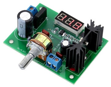
Simple voltage regulator
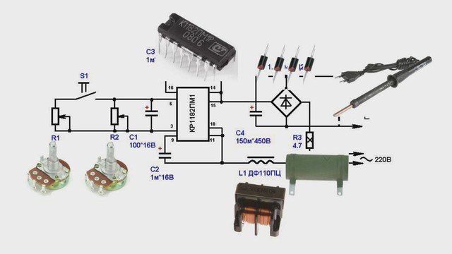
Even the simplest radio component consists of a generator, a rectifier, a battery, and also a voltage switch. Such devices usually do not contain stabilizers. The thyristor current controller itself consists of the following elements:
- diode - 4 pcs.;
- transistor - 1 pc;
- capacitor - 2 pcs.;
- resistor - 2 pcs.
To avoid overheating of the transistor, a cooling system is installed to it. It is desirable that the latter has a large power reserve, which will allow charging batteries with a low capacity in the future.
Methods for regulating the phase voltage in the network
They change alternating electric voltage with the help of such electrical devices as: thyratron, thyristor and others. When the angle of these structures changes, half-waves are applied to the load, and as a result, the effective voltage is regulated. Distortion causes an increase in current and a voltage drop. The latter changes shape from sinusoidal to non-sinusoidal.
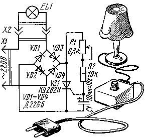
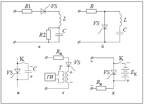
Thyristor circuits
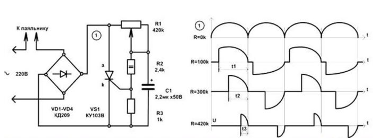
The system will turn on after enough voltage has collected on the capacitor. In this case, the opening moment is controlled by a resistor. In the diagram, it is designated as R2. The slower the capacitor charges, the greater the resistance of this element. The electric current is regulated through the control electrode.
This scheme makes it possible to control the total power in the device, since two half-periods are regulated. This is possible due to the installation of a thyristor in the diode bridge, which acts on one of the half-waves.
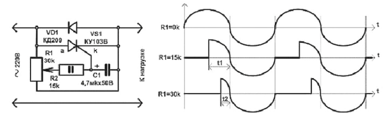
The voltage regulator, the circuit of which is presented above, has a simplified design. One half-wave is controlled here, while the other passes through VD1 without changes. It works in a similar scenario.
When working with a thyristor, a pulse should be applied to the control electrode at a certain moment so that the phase cut reaches the desired value. It is necessary to determine the transition of the half-wave to the zero level, otherwise the adjustment will not be effective.