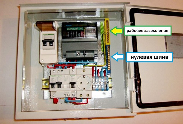
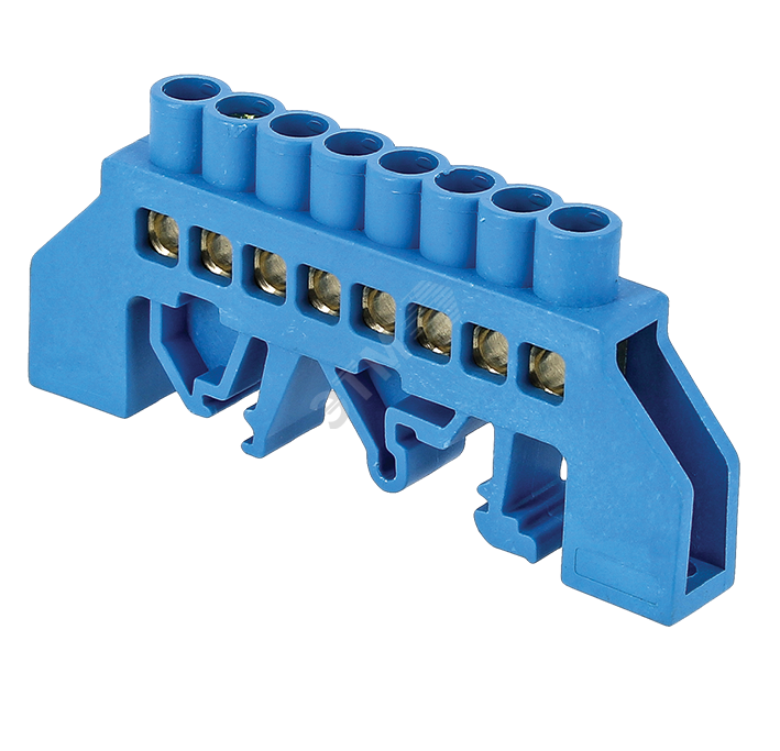
Zero bus - a contact block designed for electrical and mechanical connection of zero protective "PE", working "N" and phase network elements. Used for the proper organization of wiring in switchboards or junction boxes. Installation of the protective system is carried out on a DIN rail, electrical panel, corner insulators.
Why are different grounding systems used
 Protective grounding of the external metal parts of electrical equipment reduces the risk of electric shock due to damage to the insulator or touching dangling wires. The protective functions of grounding are based on two principles: reducing the potential difference between the grounding and neighboring conductors, as well as removing the leakage current during the interaction of the phase with the grounding wire. An abnormal situation is accompanied by an immediate operation of the residual current device - RCD.
What is the zero bus for?
The contact block solves a number of tasks:
- Fast and reliable connection of single-core, multi-core cables supplying loads. The bus allows a maximum of 40 lines with a cross section of 3 mm.
- The formation of an inextricable electrical circuit in the segment "grounding - load."
- Separation of wires for protective and working grounding.
- Improving the efficiency of switchboards.
Of particular note is the possibility of organizing a visible terminal when installing a device with a transparent cover that allows you to ground and neutralize the conductors on the respective buses.
What are zero tires
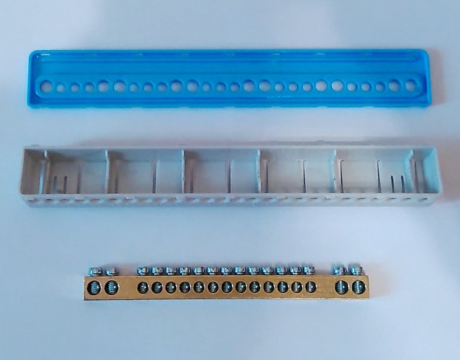
Zero tires for mounting on a metal DIN rail, G-rail or panel board are isolated and without additional protection. The insulation for the terminal is a flat PVC base or strip, equipped with two polymer "legs" (for example, ШНИ-6х9-6-У2-Ж from IEK). A bar is attached to the insulator in the center or along the edges.
-
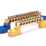
- Zero bus without additional protection
-
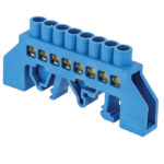
- Insulated Zero Bus
In areas requiring additional protection or the connection of several conductors: N “zero”, PE “ground”, PEN “ground-zero” we can use a polymer case, proposed in various colors: blue for neutral, yellow or green for grounding.
Design Features
The design of the zero bus is represented by a metal bar with holes and clamping contacts (bolts) that increase the safety of wiring. The functions of the conductors are performed by copper, bronze, brass elements, the insulator is a polyamide that does not support combustion. The monolithic design of the product simplifies maintenance, increases the reliability of fixation.
Zero tire performance
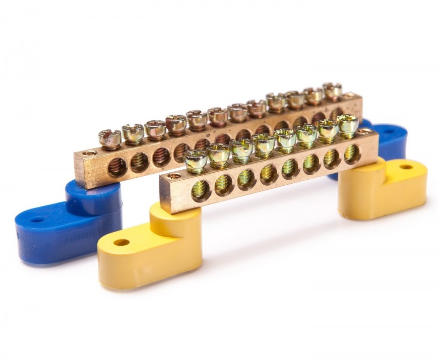
A non-insulated zero bus with sides 6 * 9mm and 8 * 12mm, length 0.5 and 1 m differ in two ways of connecting conductors: in the center or edges of the product.
The insulated zero bus with two polymer “paws” for attaching to the shield feeds wires through the upper, side openings. Sizes of bars (width / height): 6 * 9 and 8 * 12 mm.
Bus zero HCD has universal mounts: on a Din rail and the surface of the flap at the same time. The basic dimensions of the metal bar are 6 * 9 mm and 8 * 12 mm.
A zero bus with CD insulator is mounted on a din rail in the center of the product. Dimensions of the terminal 6 * 9mm, 1 m.
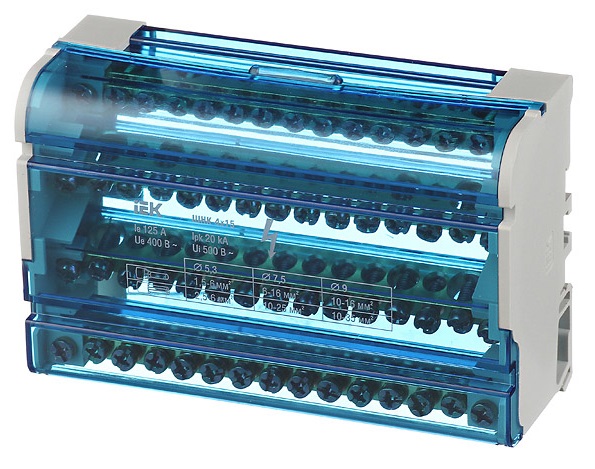
The cross-module is represented by a zero rail in the housing for mounting in a shield or 2-4 conductors in a polymer box, fixed on a DIN rail or flat surface through holes on the rear panel. The device contains holes of various diameters, allowing you to connect the wires of the corresponding sections.
The permissible current for using the cross-module in the mains is 100-125 A, the rated voltage is 500V.
Installation Rules
Installation of the simplest terminal to the shield is performed in a closed and open way. The first option prevents malicious damage to the bus of powerful or important devices, the second method is applicable in the absence of the risk of damage to the device. Zero blocks with screw connections are fixed to the distribution panel on the DIN rail, additional insulation for grounding is not provided.
The cross section of the zero and phase conductors is the same. A similar requirement is imposed on tire parameters: the size of the thinnest sections is considered to be a valid section. When combining a group of earth and zero conductors, end consumers after separation of the PEN input are connected to different buses: PE and N.
The permissible range of external temperature for the installation of conductors is -40 ... + 50 ° С, relative humidity - 90%. The rated voltage on the line is more than 400V.
What to do if there are no necessary zero tires in stock
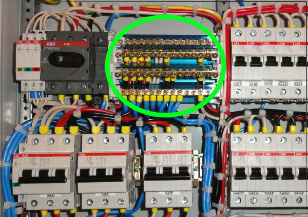
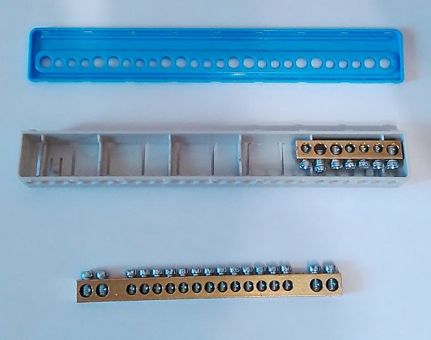
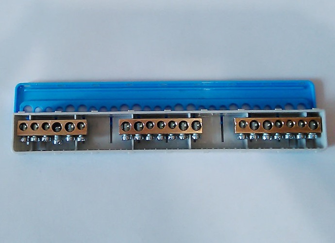
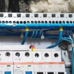
Often, distribution cabinets of imported production (ABB Mistral) are equipped with one bus "N" and "P", and if an electrician plans to ground three RCDs, he will need 3 small blocks instead of one big one. Since the dimensions of branded guards, insulated boxes exclude the placement of ordinary tires, installers have to cut the existing bar or buy for individual orders. Having immersed the received products in a plastic case, it remains to check the stability of the fastening of the brass sections.
-
- Step 1
-
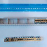
- Step 2
-
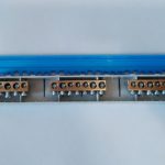
- Step 3
-
- Step 4
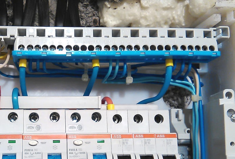
The ground bus to the DIN rail is mounted separately from the zero block, the use of a common terminal is prohibited.
How to connect multiple machines
The choice of circuit is determined by the features of a particular electrical network. The easiest way is to install one RCD immediately after the counter. A safer option is to connect protective devices on individual lines. If one device fails, the rest will remain operational. The implementation of the second scheme requires the use of a dimensional shield.
Simple circuit
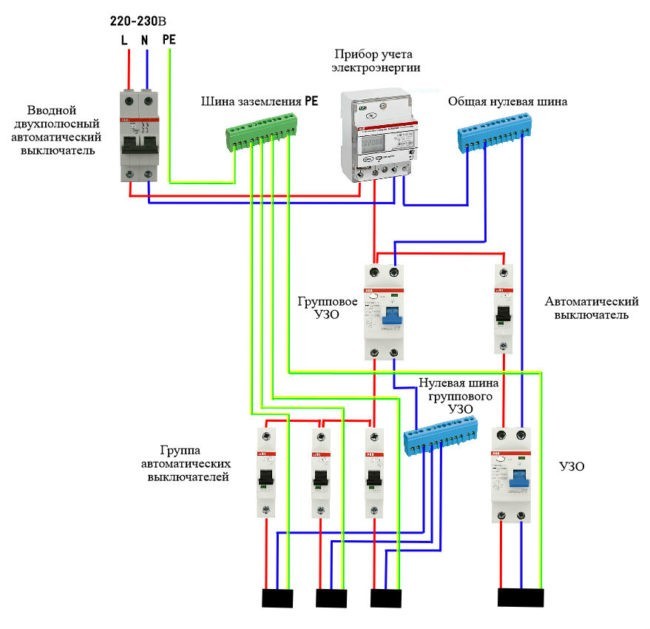
As an example, it is convenient to consider a single-phase circuit used for most apartments in multi-storey buildings. At the input, a two-pole circuit breaker is installed, connecting the RCD. The bus "0" in the electrical panel is marked "N". A two-pole residual current device is connected to two single-pole circuit breakers. The output of individual machines allows you to parallel load.
The phase connected to the circuit breaker enters the input of the RCD with the output to the circuit breakers. The zero output from the machine is sent to the corresponding bus, then to the input of the connected device. The neutral wire exiting the consumer equipment is routed to the second neutral terminal. The presence of an additional bus "0" allows the RCD to control the input and output voltage.
If two RCDs are connected, three brass blocks will be required: the main bus zero with the marking N1 and the bars N2, N3 for residual current devices. RCDs are earthed to an additional element of the electrical panel - bus "P".
Three phase network
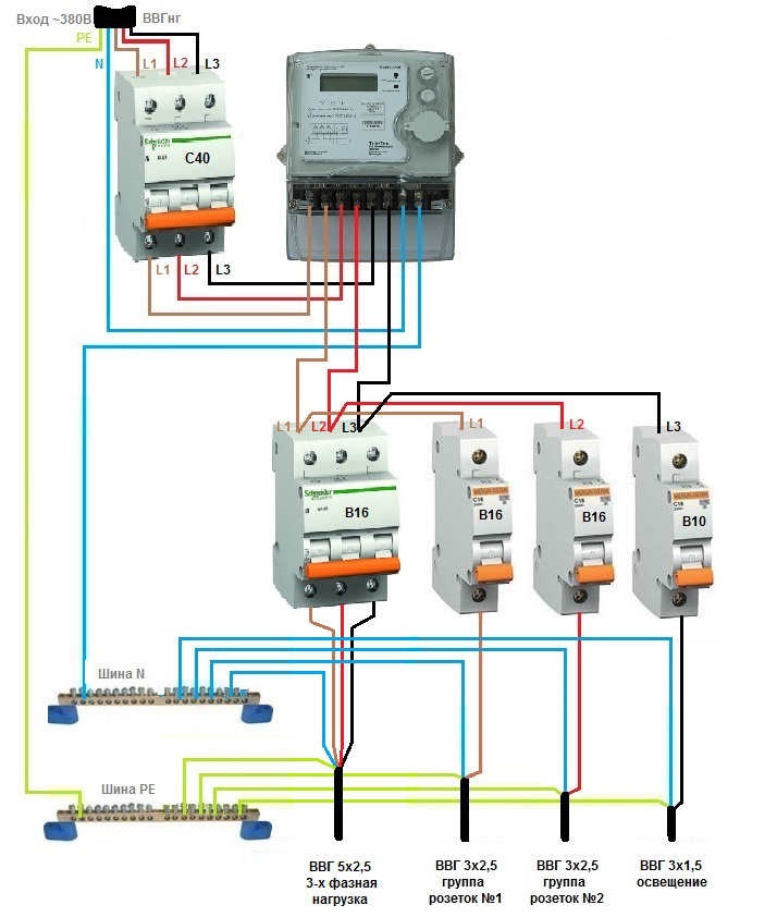
Special networks include a three-phase RCD with 8 contacts or three single-phase. The connection principle is similar, but phases A, B and C supply loads under a voltage of 380 V.
On the outgoing branches, single-phase RCDs with two poles are connected. To cover the leakage current in the range of 10-30 mA, separate automatic machines are inserted in front of the RCD. However, in the circuit after the RCD, the connection of the working zero and ground is not allowed.
Which manufacturer to choose
If the RCD, wiring, switches are made by IEK, ABB, Legrand or Schneider Elerctric - it makes sense to buy zero and grounding rails of the same brand. Extremely cheap "N" tires (zero) increase the likelihood of breakdowns, accompanied by problems for expensive electrical appliances.
The “0” bus and grounding are present in new homes connected to a three-phase network. Old buildings have a phase and zero, ground the load with a third conductor on the sockets, and then on the ceiling to the connection point of the chandelier. Switches "ground" is not served.
Installation of protection systems for a single-phase and three-phase network requires taking into account many parameters, the correct solution would be to entrust the calculation and installation of zero buses, grounding to qualified specialists.