LED lamps are becoming increasingly popular, but despite this fact, incandescent lamps are still used by millions of people, largely due to the low retail cost. This category includes not only incandescent bulbs of a traditional shape, but also halogen light sources with a base type GU4 or GU5,3.
Causes of premature burnout

In the vast majority of cases, incandescent lamps burn out when turned on, when the coil has the lowest electrical resistance. A cold filament has 10 times less resistance than a heated one. As a result, when the lamp is ignited, the current indicator reaches 8 A, which may be critical for a cold spiral.
UPVL will help extend the life of the light source - the smooth inclusion of 220 V incandescent lamps, the circuit of which is simple. The purpose of such a device is to gradually increase the voltage at the load, sudden jerks of current in the first seconds after ignition are excluded. Smooth heating of the spiral makes it possible to increase the lamp life by 2-3 times, instead of the declared 1000 hours.
Principle of operation
For a measured increase in the applied voltage, it is enough that the phase angle grows in just 2-3 seconds. The current surge is smoothed, which contributes to the smooth heating of the spiral.
When a light bulb is ignited, a half-wave of a negative type is fed through the diode, the power indicator in this case is only half the voltage. The capacitor charges in the positive half-cycle. When the voltage indicator on it rises to the opening indicator of the thyristor, the mains voltage is supplied to the light source and it glows in full heat.
Ready-made solutions
There is a lot of UPVL from Russian and foreign brands, which make it possible to realize a smooth inclusion of light. The cost of such devices depends on their functionality. Some models interact exclusively with incandescent lamps, while others additionally interact with halogen bulbs. Even budget models can carry loads up to 300 watts for a long time.
The gradual inclusion of the bulb can also be realized by means of a phase regulator. Its design is similar to UPVL, but the control system is more complex and the regulator is able to withstand heavy loads. The dimensions of the device are set by the dimensions of the radiator, which removes heat from the power component of the circuit.
Each device that guarantees the gradual ignition of incandescent lamps is connected to the electric circuit in series, in the gap of the neutral wire or phase. The voltage in the load rises a certain period of time, which is fixed and not regulated. This time is set by the manufacturer and can be up to 3 seconds.
Wiring diagrams
For smooth ignition of the bulb to be effective, a special electrical circuit is needed. With its help, you can understand how UPVL functions and what its internal structure is.
Usually, when connecting such a device, the simplest thyristor circuits are used. A special scheme with an integrated triac is somewhat less commonly used. In addition to these blocks, field-effect transistors can be used, which operate similarly to gradual switching devices.
220V lamp flickering: thyristor circuit
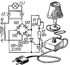
The thyristor circuit is simple and easy to make on your own.
The rectifier bridge circuit uses the lamp as a load and current limiter. On the shoulders of the rectifier, a moving type circuit and a thyristor are installed. The installation of a diode bridge is determined by the specification of the thyristor.
After applying voltage to the circuit, current begins to flow through the filament and comes to the bridge, while the electrolyte is charged with a resistor in the meantime. It begins to open when the thyristor voltage limit is reached, after which current from the lamp passes through it. As a result, the tungsten filament warms up smoothly. The time of its heating directly depends on the capacitance of the capacitor and the resistor built into the circuit.
Smooth on lamps 220 V: circuit on the triac
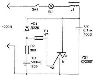
This circuit has fewer components due to the use of the triac as a power key.
The throttle, designed to eliminate a variety of interference when opening the power key, can be removed from the common network. The current supplied to the main electrode is limited by a resistor. The timing circuit is implemented on the capacitance and resistor, which are powered by a diode.
The presented scheme functions similarly to the previous one. The capacitor opens when it is charged to the magnitude of the opening voltage of the triac, and then through it the current flows to the lamp.
Scheme on a specialized chip
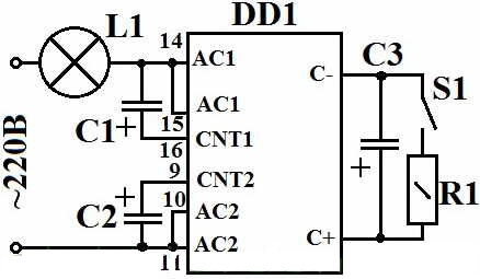
To create a controller for smooth ignition of lamps, you can use a special chip marking kr1182pm1.
In this design, the chip itself adjusts the voltage on the lamp with a filament with a power of up to 150W. To control a higher load, a greater number of lighting devices simultaneously in the control chain you need to include an auxiliary power triac.
These devices are able to smoothly turn on not only incandescent bulbs, but also halogen ones at 220 V. Phase controllers are also installed in an electric tool, they smoothly start the motor armature, extending the life of the devices several times.
It is strictly forbidden to install the dimmer for an incandescent lamp in conjunction with fluorescent and LED lamps. Their principle of operation and circuitry are completely different. Each of these lamps has its own gradual heating device.
Connection using a protection unit
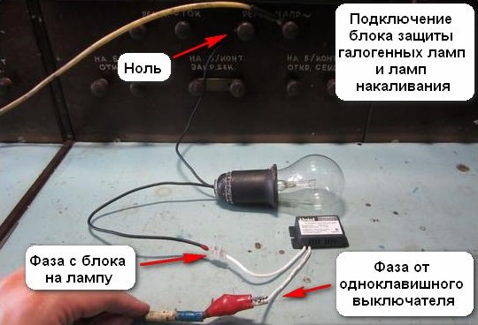 Schematic connection to the network of the protection unit will not cause labor when installing the device. The device is connected in two different ways, which directly depends on the voltage of the applied bulbs.
If 220 V lamps are used in the lighting fixtures, the protection unit is connected in series with the circuit. The polarity of the wiring does not matter, the main thing is that the unit must be connected to the wire break with a phase, that is, in series with the switch.
If the lamps used have a lower voltage (6 -24 V) and are connected to the network via a step-down transformer, the protection unit must be connected on the 220 V input side.
How to make a protection unit yourself
You can create a protection block in the following way:
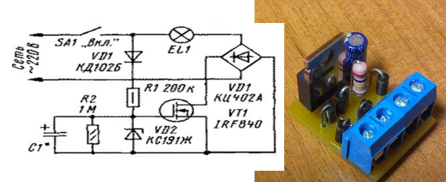
The principle of operation of the unit:
- At the start, the field effect transistor is in the closed state. It receives stabilization voltage. The light does not light up.
- The resistor (R1) and the diode (VD1) transmit the voltage to the capacitor (C1), as a result of which it starts to charge up to 9.1 V. This is the limit indicator, limited by the characteristics of the zener diode.
- When the set voltage is reached, the transistor begins to open, and the current strength increases. In the current state, the voltage decreases, and the spiral of the bulb begins to gradually warm up.
- The discharge level of the capacitor is controlled by a second resistor. Due to this, the capacitor continues to discharge after disconnecting the power.
The use of a protection unit makes it possible to gradually start lamps with a filament.It protects them from negative flicker during operation.