Not a single electrotechnical device with a protective function will be able to operate normally without a special trigger - a release. It is a special structural element built into a circuit breaker or connected to it by a common electrical circuit. When the machine operates, it releases the latch that holds the actuating unit from switching. Due to the action of the voltage (current) release, the circuit breaker trips in automatic mode, after which the circuit in which it is installed is completely de-energized.
When e / m and thermal releases are triggered
 The electromagnetic release integrated in the circuit breaker operates in the following emergency situations:
- in case of a malfunction of the machine that ceases to fix the switch;
- with a significant excess of the load current rating;
- with sharp fluctuations in the voltage in the network;
- in the case of short circuit, leading to the appearance of overcurrents.
Automatic releases also work when there is a malfunction of the equipment being protected - when current leaks to the case or to the ground appear in it.
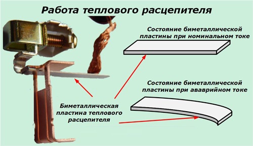
The thermal device has a bimetallic spring, individual parts of which, when significant currents flow through them, are heated with a different expansion coefficient. When heating one end of the spring, it lengthens slightly less than the other, which leads to bending of the element and the release of the trigger mechanism.
The thermal release is installed in the gap of the controlled circuit. It protects it from current overloads and adjusts to pre-set operation modes.
Device design
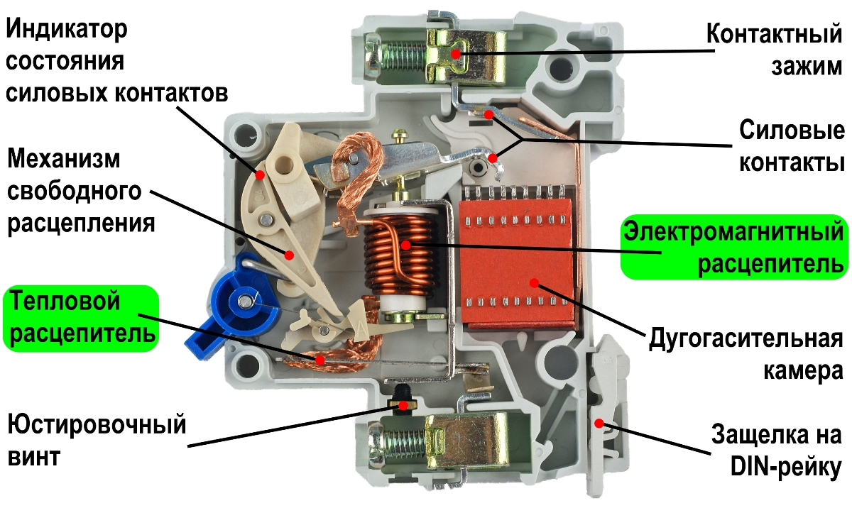
The design and general arrangement of an automatically activated release are primarily dependent on its type. The thermal release mechanism is a bimetallic plate capable of bending when heated. It is made by mechanical connection (welding) of two metal billets from materials with different coefficients of thermal expansion. During mechanical deformation, one of its ends acts on the mechanism of free disengagement and causes it to turn off.
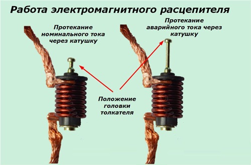
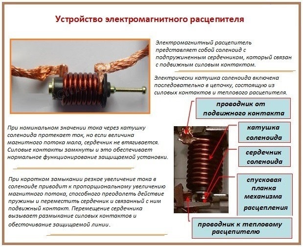
In contrast, the magnetic device operates on the principle of an electromagnet that operates under certain conditions. A special spring is provided in its design, which prevents instant contact opening. As soon as the current strength reaches a value sufficient to overcome this resistance, the lock is released from the actuator. This node opens the working circuit of the circuit breaker, removing the voltage from the load (leaving the consumer without current). Most often, electromagnetic trip devices protect the supply lines from short circuits.
Varieties of releases
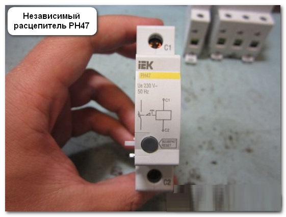
 Known types of releases used in circuit breakers, according to their functional purpose, are divided into independent devices and maximum current devices. The first ones allow you to control the shutdown of protective equipment remotely and are used in combination with a certain type of circuit breaker with a voltage relay installed in it.
Overcurrent releases are located directly in the AB housing, being their structural element. This type of devices that ensure the release of the actuators AB, is divided in turn into the following types:
- thermal release (for overcurrent);
- its electromagnetic analogue (according to short circuit);
- a combination of these two devices;
- semiconductor or electronic release.
Very often, two or more trip devices are installed in one AB at once.
Automatic machines with the first two types of trip units, built directly into their housing, are usually used to protect 380 Volt power lines (they are called combined). This type of trip device is also installed in the supply circuits of induction motors, where the protection is built on a two-stage circuit. When they are started in the nominal (permissible) modes, the thermal release is activated, however, the circuit is not completely de-energized. And only when the current reaches the limit (emergency) value, after the thermal, the e / m stage is triggered, finally disconnecting the motor from the three-phase network.
Both thermal and electromagnetic releases are installed in each of the supply phases of the induction motor and can operate independently of one another.
In addition to purely mechanical trip devices in electrical engineering, their electronic counterparts are increasingly being used, the principle of operation of which is based on the key properties of their constituent elements. As the keys, power transistors are usually used, the semiconductor junction of which is a controlled analogue of the trigger device. With the help of such a circuit, an actuating unit (usually a relay or an electronic one) is started, disconnecting the emergency circuit.
Installation procedure for the release
 The circuit breaker trip unit as a whole integrates into the circuit being serviced together with the protective device. At the same time, its thermal contacts or electromagnetic breaker together with a tap to the coil are connected to the input and output terminals. The combined device is mounted on the din-rail of the distribution cabinet or on the allocated place of the apartment panel. It is installed immediately after the electric meter, from which a separate phase wire is laid towards the machine. From the circuit breaker itself, the switched phase “forwards” to the final load (outlet or light switch).
The zero core is laid around the machine with a trip element, since for their normal operation it is not necessary.
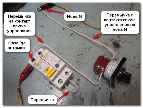
A different picture is observed when mounting a circuit breaker with an independent trip, which is located separately from the main device. In this case, it is necessary to lay additional wiring and switch the device according to the electrical circuit attached to it. These wires during operation and control signals are transmitted to the executive module.
The inclusion in the power circuit of the machine itself is carried out according to the standard scheme, according to which the following options are possible:
- installation of three separate automatic devices (one for each phase);
- installation of a 3-pole three-phase switch (without zero terminal);
- use of a 4-pole model (with zero contact).
Regardless of the installation method chosen, an automatic device with an independent trip unit is connected directly to the controlled circuit, reacting to currents flowing through it.
Health Check
Before starting a technical check of the releases, first of all, an external inspection of the AB is carried out for chips, cracks and other damages on its body. After this, they proceed to assess the state of insulation resistance of current-carrying conductors and connecting wires.
Requirements for the control measurement of this parameter are stipulated in clause 1.8.37.3 of the PUE.
For these purposes, the following types of measuring instruments, differing in the ratings of the controlled voltages, are suitable:
- Megaohmmeter under the designation M4100 / 5 (measuring voltage - 2500 Volts).
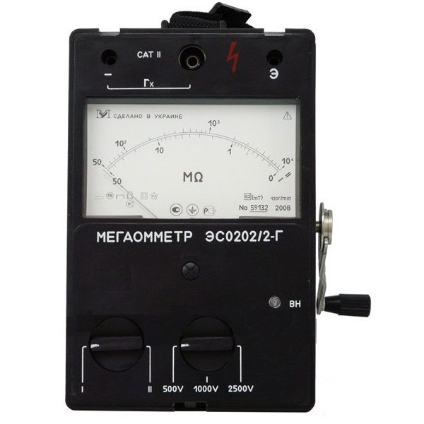
- ESO202 / 2 device with voltage from 500 to 2500 Volts.
- F4102 / 1-1M meter with the same voltage ratings.
- A MIC-2500 device with an operating voltage of 50 to 2500 Volts.
Either the M4100 / 5 or the MIC-2500 are ideal for checking releases from this list. Before starting measurements, you should also provide for a reliable fixation of the machine disconnected from the network on a grounded metal base, and then prepare for the inspection of its pole. Isolation between each of the AB poles and the earthing contact is to be measured. According to the requirements of the PUE (clause 1.8.37.3), its resistance for this section cannot be less than 1 MΩ, and in PTEEP this parameter must be maintained at a level of at least 0.5 MΩ.
Even a superficial acquaintance with the known types of releases of circuit breakers shows how wide the range of these devices is. Despite the wide variety of names of switching devices, which differ not only in the principle of action, but also in their design, they all perform the same function. It consists in the timely removal of locks from the actuator of the machine.