In modern life, it is impossible to do without household appliances and electronic equipment, the amount of which is constantly growing every year. This leads to an increase in energy consumption from the existing power grid and the need to control its operating parameters. Of particular importance is the issue in suburban housing, where 380 volts are allowed. For this reason, various options for connecting three-phase electricity in private homes are subject to serious research.
Single phase and three phase connection
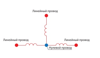
When clarifying the differences in the quality of the two types of power supply (with one- and three-phase connection) and the associated circuit solutions, the following should be noted:
- when using a three-phase system, a cable with 4 wires is required for laying the line, with a grounding loop with 5 wires, and for a single-phase method, three wires are enough;
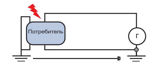
 Single Phase Connection Diagram
 - in the first case, the cost of cable products will increase, as well as the purchase of service equipment - a three-phase electric meter, automatic machines and RCDs are more expensive than their single-phase counterparts;
- the power consumed by the substation will increase markedly, which is explained by significantly increased loads in the 380 Volt network.
These differences are taken into account when preparing a project for power supply of a private house. Important factors such as current distribution and power loss in a three-phase load due to its reactive nature are also taken into account.
Connection project and necessary documentation
The power supply project of a private house of 15 kW 3 phases includes several sections, each of which relates to a certain stage of implementation. At the preparatory stage, the following mandatory activities are carried out:
- preparation and approval of permits;
- drawing of the electrical circuit and the choice of consumers for power in reactive load;
- breaking them down into separate groups.
Without a thorough preliminary study of all the intricacies of the project, it is unlikely that it will be possible to approve a set of working documentation. Therefore, each of the stages of its preparation needs a separate consideration.
Preparation of documentation

The package of permits is completed on the basis of specifications that determine the arrangement and operation of a three-phase network. They are issued by representatives of the local Energosbyt. Based on the technical conditions, the following documents are executed:
- an agreement with a regional electricity supplier;
- inspection certificate of operating equipment;
- a conclusion on the functionality of the circuit selected for a particular object;
- act of demarcation of existing power grids by their balance sheet affiliation.
In addition, at this stage of designing, the features of the operation of specific consumers of electricity - pumping and machine equipment in particular, are taken into account.
Scheme and power selection
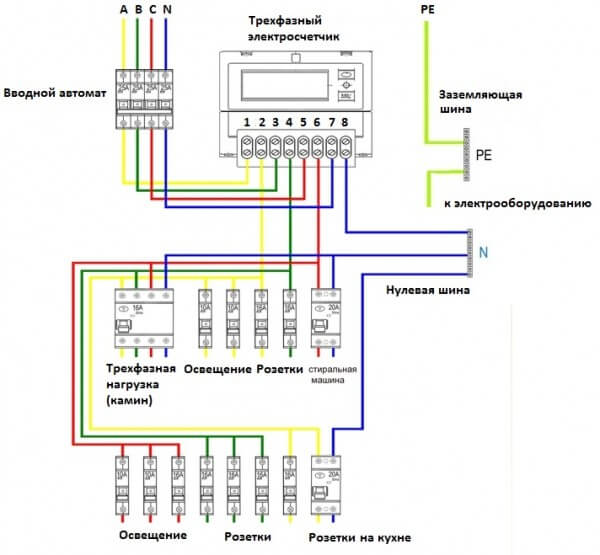
When drawing three-phase electricity connection diagrams in private homes, the following details should be considered:
- It must indicate the route of the strip, the type and main characteristics of the wiring cable, as well as the location of the wiring products.
- The same is done with respect to protective equipment: electricity meter, input and distribution machines, as well as RCDs.
- The diagram also indicates the type of current protection system used (wiring method for PE and N conductors), as well as the need for re-grounding.
In addition, reference is made to the use of additional protective equipment - a voltage monitoring relay in particular.
Calculation of power consumption in kilowatts is performed according to a standard algorithm, according to which all indicators for the estimated loads are simply added up.
For “reactive” consumers (three-phase pumps, machine tools and other equipment equipped with induction motors), a correction factor called the power cosine is introduced. Its averaged over loads value is 0.97-0.98.
Grouping

All consumers indicated on the 15 kW power supply scheme of the house (sockets and lighting fixtures) are divided into separate groups. Such a partition is very convenient for repair and maintenance of an equipped power supply system. For the functioning of each of these groups, a separate circuit breaker installed in the electrical panel is “responsible”. With it, if repair is necessary, for example, you can disable only this branch of the wiring, leaving all the others in working condition.
For each such group, the calculation of the maximum power consumption is done separately. Based on the data obtained, a suitable automaton is selected for the rated current. In addition, they are the basis for selecting the cross-section of the conductors for this branch of the home electrical network.
Lighting lines are laid with a typical wire with a core cross section of at least 1.5 mm2, and in the electrical wiring for connecting outlets it will be necessary to increase this parameter to 2.5 mm2.
All these data are necessary in order to connect the serviced object to the power system in accordance with the requirements of the EMP. If available, it will be much easier to determine the amount of consumables, protective devices and other samples of electrical equipment.
Features of the distribution panel
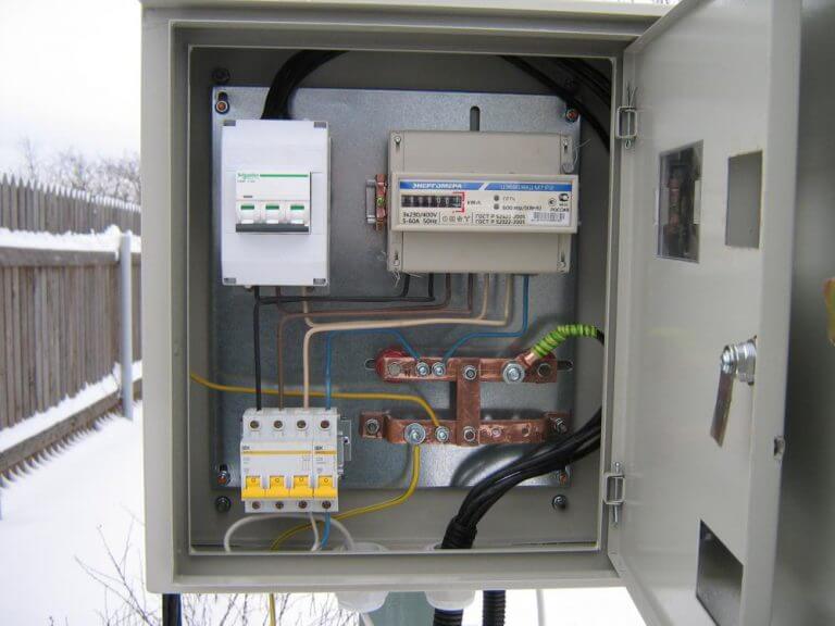
A single-line scheme of a 15 kW 380V metering panel (as a special case) is the most common option for building this part of the power supply system. When arranging it, the following configuration options are considered, taking into account the differences in single-phase and three-phase power supplies:
- The use of standard unipolar circuit breakers and RCDs as protective equipment (one for each phase).
- The use of 4-pole differential devices in the circuit.
- Installation of two-pole automatic machines in the shield, supplemented by a cross-module and RCD.
- Installation of single-pole linear circuit breakers together with a 4-pole RCD and a cross module.
Each of these options, if there is space in the shield, is suitable for arranging and connecting a full three-phase power supply system. The choice of a specific set of switching devices depends on the preferences and financial capabilities of the owner of suburban housing.
Wiring Test
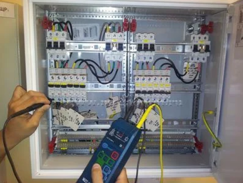
At the end of the wiring installation, it is mandatory to check for operability, which is reduced to the following operations:
- First of all, one should “try on” the parameters selected by calculation by current and maximum power to the actual operating conditions of electrical equipment.
- To do this, you will need to turn on all the electrical appliances indicated in the project at the same time and check the wiring for insulation heating.
- If the conductors are a little warm to the touch, and the machines do not constantly knock out, we can say with confidence that all parameters are selected correctly and the system is ready for operation in normal mode.
When the test program is fully exhausted, they proceed to the final arrangement of energy supply elements.At the final stage, all contact connections in the mounting blocks are checked once more and the operation limits of the RCD and voltage relays are adjusted, adjusted according to the results of test procedures.