When arranging a new apartment or house, updating or repairing housing, one has to deal with elements intended for the flow of electric current. It is important to know what an electric circuit is, what it consists of, why a circuit is needed, and what calculations need to be performed.
What are electrical circuits?
An electric circuit is a complex of various elements interconnected. It is designed for the flow of electric current, where transients occur. The motion of electrons is provided by the presence of a potential difference and can be described using terms such as voltage and current.
The internal circuit is provided by connecting voltage as a power source. The remaining elements form an external network. For the movement of charges in the field power source, an external force is required. It can be a winding of a generator, transformer or galvanic source.
For such a system to function correctly, its circuit must be closed, otherwise the current will not flow. This is a prerequisite for the coordinated operation of all devices. Not every circuit can be an electrical circuit. For example, grounding or protection lines are not such, since in normal mode no current flows through them. They can be called electric according to the principle of action. In an emergency, current flows through them, and the circuit closes, leaving the ground.
Depending on the power source, the voltage in the circuit may be constant or variable. The battery of elements gives a constant voltage, and the windings of generators or transformers give an alternating voltage.
Main components
All components in the circuit are involved in one electromagnetic process. They are conditionally divided into three groups.
- Primary sources of electrical energy and signals can convert non-electromagnetic energy into electrical energy. For example, a galvanic cell, a battery, an electromechanical generator.
- The secondary type, both at the input and at the output, has electrical energy. Only its parameters change - voltage and current, their shape, magnitude and frequency. Examples include rectifiers, inverters, transformers.
- Consumers of active energy convert electrical current into lighting or heat. These are electrothermal devices, lamps, resistors, electric motors.
- Auxiliary components include switching devices, measuring instruments, connecting elements and a wire.
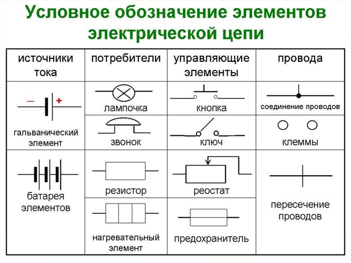
 The basis of the electrical network is the circuit. This is a graphic drawing that contains conditional images and designations of elements and their connection. They are carried out according to GOST 2.721-74 - 2.758-81
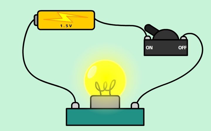
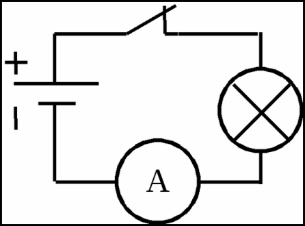
The simplest circuit diagram includes a galvanic cell. By means of wires, an incandescent lamp is connected to it through a switch. To measure current and voltage, a voltmeter and an ammeter are included in it.
Circuit classification
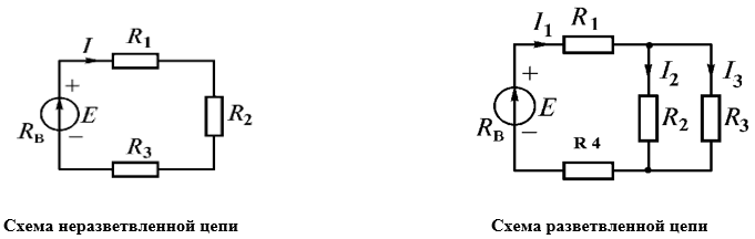
Electric circuits are classified by type of complexity: simple (unbranched) and complex (branched). There is a division into DC and AC circuits, as well as sinusoidal and non-sinusoidal. Based on the nature of the elements, they are linear and non-linear. AC lines can be single-phase and three-phase.
Branched and unbranched
In all elements of an unbranched circuit, the same current flows.The simplest branched line includes three branches and two nodes. Each branch has its own current. A branch is defined as a section of a chain that is formed by series-connected elements enclosed between two nodes. A node is the point at which the three branches converge.
If there is a dot on the diagram at the intersection of two lines, there is an electrical connection of two lines at this point. If the node is not marked, the chain is unbranched.
Linear and nonlinear
An electrical circuit in which consumers are independent of the voltage value and current direction, and all components are linear, is called linear. Elements of such a circuit include dependent and independent sources of currents and voltages. In linear, the resistance of an element does not depend on current, for example, an electric furnace.
In non-linear, passive elements depend on the values of the direction of currents and voltage, have at least one non-linear element. For example, the resistance of an incandescent lamp depends on voltage surges and amperage.
Designations of elements in the diagram
 Before proceeding with the installation of equipment, it is necessary to study the regulatory accompanying documents. The scheme allows you to convey to the user the full characteristics of the product using alphabetic and graphic designations entered in a single register of design documentation.
Additional documents are attached to the drawing. Their list can be indicated in alphabetical order with digital sorting on the drawing itself, or as a separate sheet. Classify ten types of circuits, in electrical engineering usually use three main circuits.
- Functional has minimal detail. The main functions of the nodes are represented by a rectangle with letter designations.
- The circuit diagram in detail displays the design of the elements used, as well as their connections and contacts. The necessary parameters can be displayed directly on the diagram or in a separate document. If only part of the installation is indicated, this is a single-line diagram, when all elements are indicated - complete.
- In the wiring diagram use the positional designations of the elements, their location, installation method and order.
To read the wiring diagrams, you need to know the graphic symbols. The wires that connect the elements are represented by lines. A solid line is a generic term for wiring. Above it may be indicated data on the laying method, material, voltage, current. For a single-line circuit, a group of conductors is represented by a dashed line. At the beginning and at the end indicate the marking of the wire and the place of its connection.
Vertical notches on the wiring line indicate the number of conductors. If there are more than three, perform a digital designation. The dashed line indicates control circuits, a network of security, evacuation, emergency lighting.
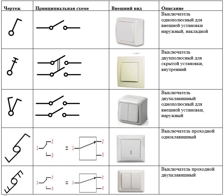
The switch in the diagram looks like a circle with a slant to the right. The type and number of dashes determine the parameters of the device.
In addition to the main drawings, there are equivalent circuits.
Three phase electrical circuits
Among electrical circuits, both single-phase and multiphase systems are common. Each part of a multiphase circuit is characterized by the same current value and is called a phase. Electrical engineering distinguishes between two concepts of this term. The first is the direct component of a three-phase system. The second is a value that varies sinusoidally.
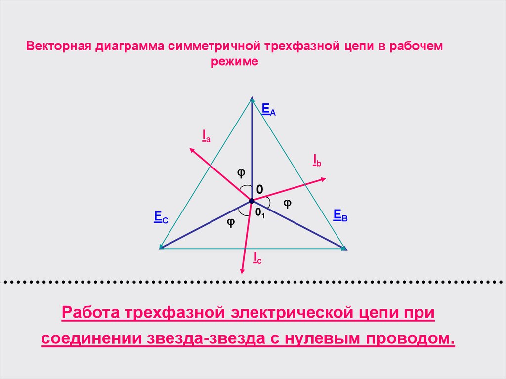
A three-phase circuit is one of the multiphase AC systems, where sinusoidal EMFs (electromotive forces) of the same frequency act, which are shifted in time relative to each other by a certain phase angle. It is formed by the windings of a three-phase generator, three power receivers and connecting wires.
Such circuits serve to ensure the generation of electrical energy, for its transmission, distribution, and has the following advantages:
- profitability of electricity generation and transportation in comparison with a single-phase system;
- simple magnetic field generation, which is necessary for the operation of a three-phase asynchronous electric motor;
- the same generator set gives out two operational voltages - linear and phase.
The three-phase system is advantageous when transmitting electricity over long distances. In addition, the material consumption is much lower than single-phase. The main consumers are transformers, induction motors, converters, induction furnaces, powerful heating and power plants. Among single-phase low-power devices, one can note power tools, incandescent lamps, household appliances, power supplies.
The three-phase circuit is characterized by a significant balance of the system. The methods of connecting the phases have received the structure of "star" and "triangle". Usually, the phases of generating electric machines are connected by a “star”, and the phases of consumers by a “star” and a “triangle”.
Laws in force in electrical circuits
 In the diagrams, the direction of the currents is indicated by arrows. To calculate, you need to take directions for voltages, currents, EMF. When calculating in electrical engineering, the following basic laws are used:
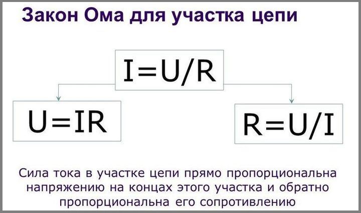
- Ohm's law for a straight section of the circuit, which determines the relationship between the electromotive force, the voltage of the source with the current flowing in the conductor and the resistance of the conductor.
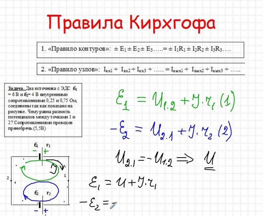
- To find all currents and voltages, use the Kirchhoff rules, which operate between the currents and voltages of any part of the electric circuit.
- The Joule – Lenz law quantifies the thermal effect of an electric current.
In DC circuits, the direction of action of the electromotive force indicates from a negative potential to a positive one. For the direction take the movement of positive charges. In this case, the arrow is directed from a larger potential to a smaller one. The voltage is always directed in the same direction as the current.
In sinusoidal EMF circuits, voltage and current are indicated using a half-cycle of current, while it does not change its direction. To emphasize the potential difference, they are indicated by the signs “+” and “-”.
How is electrical circuit calculated?
 The calculation path is divided into many methods that are used in practice:
- a method based on Ohm's law and the rules of Kirchhoff;
- a method for determining loop currents;
- reception of equivalent transformations;
- methodology for measuring the resistance of protective conductors;
- calculation of nodal potentials;
- identical generator method, and others.
The basis for calculating a simple electric circuit according to Ohm's law is to determine the current strength in a separate section with a known resistance of conductors and a given voltage.
By the condition of the problem, the resistances of the resistors R1, R2, R3, R4, R5, R6 connected to the circuit are known (excluding the resistance of the ammeter). It is necessary to calculate the current strength J1, J2 ... J6.
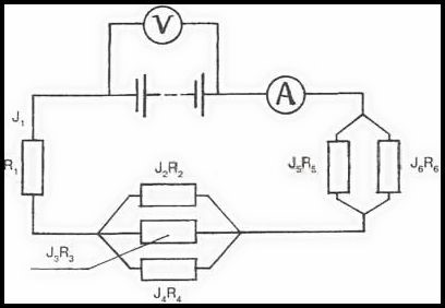
There are three consecutive sections in the diagram. Moreover, the second and third have branches. The resistances of these sections are denoted as R1, R ’, R”. Then the total resistance is equal to the sum of the resistances:
R = R1 + R ’+ R”where
R ’ - total resistance of parallel connected resistors R2, R3, R4.
R ” - total resistance of resistors R5 and R6.
Using the law of parallel connection, we calculate the resistance R ’and R”.
1 / R ’= 1 / R2 + 1 / R3 + 1 / R4
1 / R ”= 1 / R5 + 1 / R6
To determine the strength of the current in an unbranched circuit, knowing the total resistance at a given voltage, you can use the following formula:
I = U / R, then I = I1
To calculate the current strength in individual branches, you need to determine the voltage on sections of sequential circuits according to Ohm's law:
U1 = IR1; U2 = IR ’; U3 = IR ”;
Knowing the voltage of specific sections, it is possible to calculate the current strength on individual branches:
I2 = U2 / R2; I3 = U2 / R3; I4 = U2 / R4; I5 = U3 / R5; I6 = U3 / R6
Sometimes it is necessary to find out the resistance of sections by known parameters of voltage, current strength, resistance of other sections, or make a calculation of the voltage from the available resistance and current data.
The main part of the methods is aimed at simplifying the calculations. This is achieved by adapting systems of equations, or the scheme itself. The calculation of electrical circuits is carried out in various ways, depending on the class of their complexity.