Power surges can damage electrical appliances. To prevent this from happening, special devices are used - voltage stabilizers. They protect the power supply network from interference, unstable power supply and give the devices necessary for operation 220 V. Stabilizers are especially needed in a country house or cottage, since it is outside the city environment that an unstable network is most often found. Stabilizers can be used both for simple household appliances (TV, refrigerator), and for devices with high power.
Types of stabilizers
All voltage stabilizing devices can be divided into several categories:
- electromechanical;
- relay;
- magnetoelectric;
- pulse converters.
Switching transformer windings in an electromechanical stabilizer is performed using a motor. The sliding block corrects the applied voltage. The disadvantage of the system is its large dimensions. Also large are relay and magnetoelectric devices. This is due to the presence of a large transformer for voltage equalization.
If you need a compact device, it is better to choose a pulse device. It costs more, since there are special inverters in the design.
The choice of a specific model directly depends on the installation location and the financial capabilities of the user.
Gear stages
Any leveling device has switching steps. They determine the quality of the output electricity. At a normal voltage of 200 V, electricity is passed through the circuit without changes. If the voltage drops (for example, up to 190 V), the first stage is switched on, at which the load is converted to the required 220 V. The lower the current voltage, the higher the stabilizer switches. If all the steps have ended, raising the voltage will not work.
Necessary materials
 To connect, you need the stabilizer itself. It must be selected in advance, taking into account which device will be connected to it. The following materials are also needed:
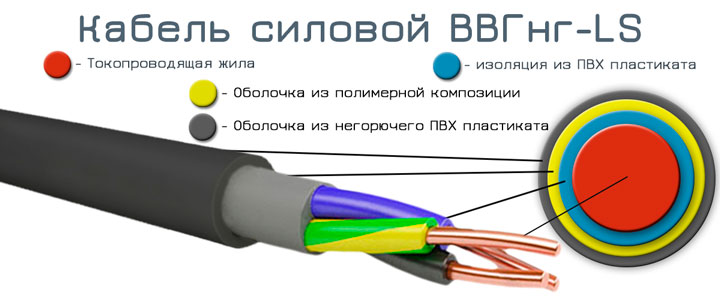
- Three-core cable VVG. Its cross-section must coincide with the cross-section of the input cable on the knife switch or input automatic machine.
- Three-position switch to activate the stabilizer. It has 3 states - the first consumer is on, the second consumer is on and off. Instead, you can use the usual modular switch, but in this case, when disconnected from the stabilizer, the entire room will be de-energized each time.
- PUGV wires of different colors.
The stabilizer must be mounted before the energy meter. Other connection is prohibited. This is due to the fact that the stabilizer has its idle and consumes electricity. It should be taken into account when paying bills.
It is also recommended that in the circuit, before connecting the stabilizer, put an RCD or a differential machine.
Choosing an installation location
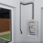
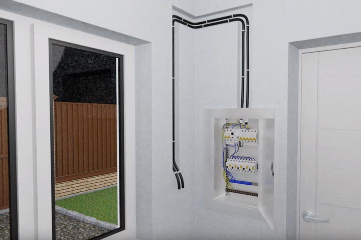
It is necessary to pre-select the place in which the stabilizer will be installed. The dimensions of the device are determined by its output power. Small stabilizers can be installed next to the equipment on the table. Oversized models require fixed installation. The installation site may be a floor, wall or pre-equipped niche.
Running transformers heat up, which is why it is necessary to conduct a heat removal system.For this reason, the stabilizer should be installed in a place where access to the ventilation openings will be open. Then the necessary air exchange will be created inside.
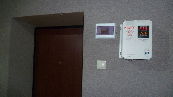
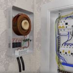
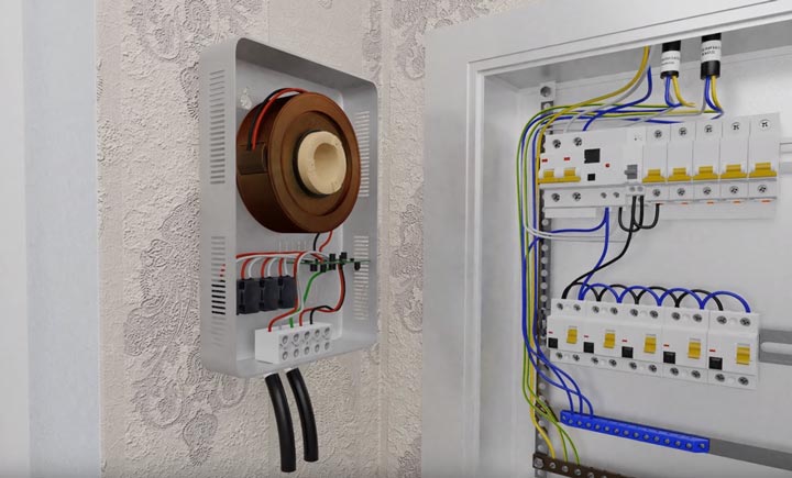
The installation site should be dust free, without humid air, away from flammable and combustible liquids. High temperatures, dust, moisture can damage the stabilizer. The optimal location is to install next to the junction box at the entrance to the meter.
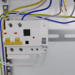
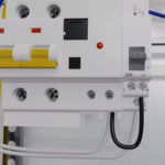
Switchboard connection
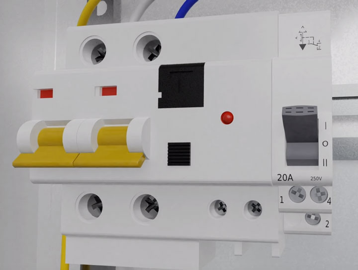
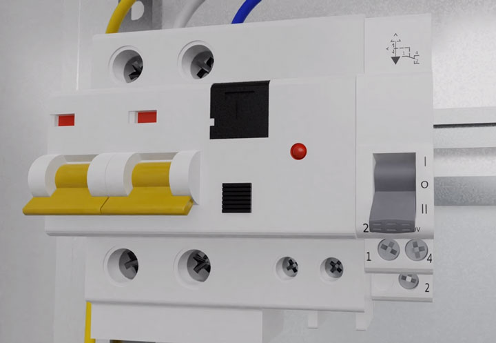
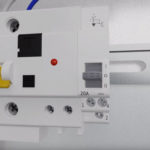
After the machine, a three-position switch must be installed in the shield. In position 1, with the lever raised up, voltage is supplied directly from the network, without using a voltage regulator. This mode is used if the voltage regulator is broken or revision work is being carried out.
In position 2, with the lever pointing down, electricity goes through the stabilizer. In the zero position, all devices are disconnected from the stabilizer and from the mains.
-
- Position I
-
- Regulation II
-
- Position 0
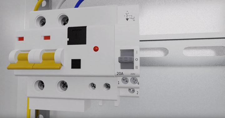
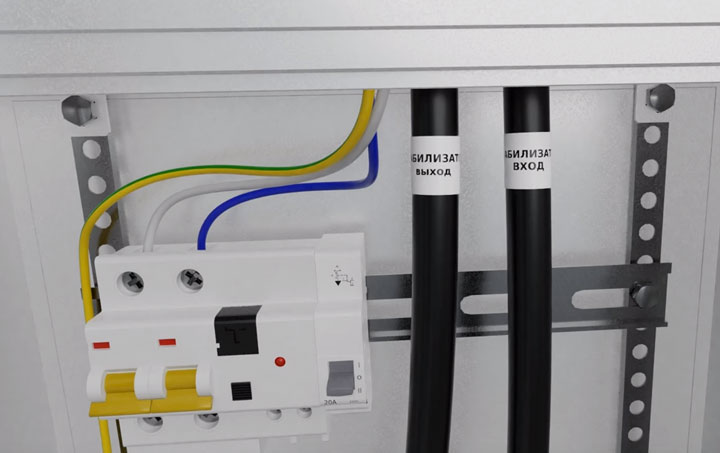
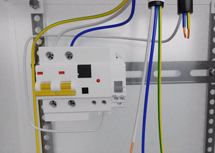
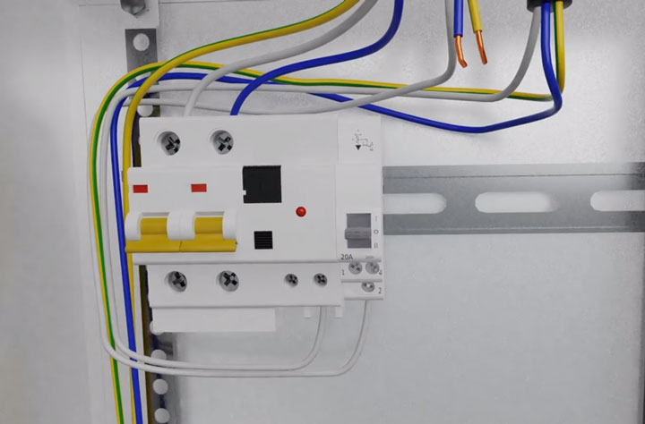
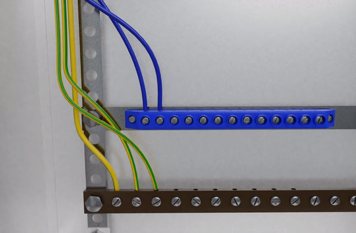
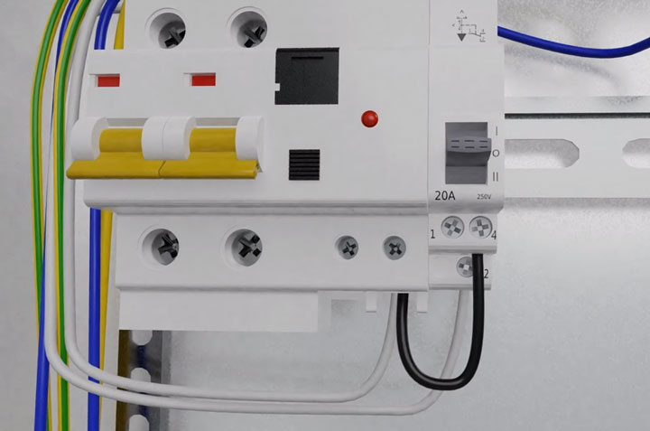
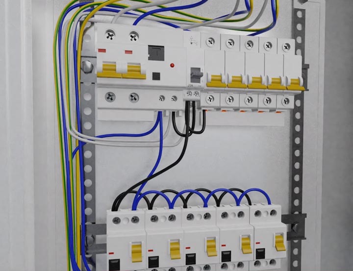
From the shield to the selected installation location, two VVG cables are laid. For convenience, they need to be marked: the entrance to the stabilizer and the output. Part of the insulation is cleaned from the cores and connected to the electrical panel. The phase from the input of the stabilizer goes to the output terminal of the difavomat. The output phase goes to pin 2 on the three-position switch. Zeros and earths from both wires are connected to the respective buses.
After the phase, the machine goes to the three-position switch. The PUGV mounting wire must be stripped from the insulating layer, terminated with a tip and turned on from the phase of the machine to the 4 clamp of the switch.
The last step is to power the machine from terminal 1 of the three-position device. This is also done with a flexible mounting cable.
-
- Cable laying VVGnG-Ls
-
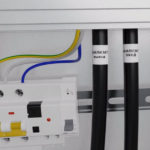
- Cable marking
-
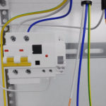
- Phase connection from the stabilizer to the input circuit breaker
-
- Phase connection to pin No. 2
-
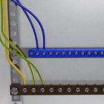
- Ground and ground connection
-
- Institution of a core of a phase output of an input automatic machine at clamp No. 4
-
- Powering all automatic machines from terminal No. 1 of the three-positioner
-
- Cable clamp (input and output) for terminals
Before connecting, be sure to check the consistency of contacts in the documentation. They may vary between models.
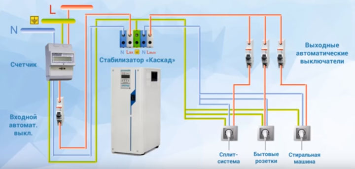
Wire connection
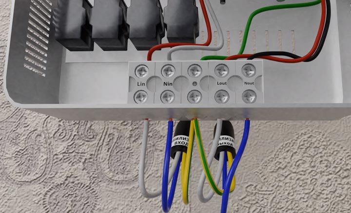
To connect, remove the protective cover on the stabilizer. The input and output cables are threaded through the hole and clamped using terminals. The phase of the input cable must be connected to the input of the Lin stabilizer. Zero to terminal N. Earth to the appropriate terminal. If there is no earth, the core is twisted under the screw of the device casing.
After applying voltage from the junction box, stabilized power must be supplied back to the shield. To do this, connect through the output cable from the stabilizer. Phase - to the output Lout, zero - to N, ground - to the same place where the grounding conductor from the input cable is connected.
The last step is a visual inspection of the connection and testing the system.
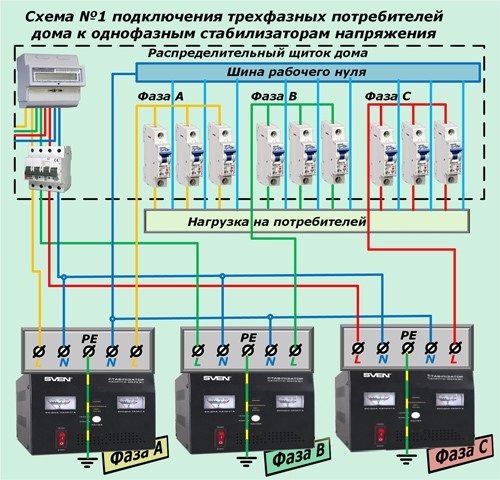
Features of connecting the stabilizer to a three-phase network
Three-phase stabilizers for each unit have their own terminal blocks. When they are included in the network, a uniform distribution of single-phase consumers should be performed. This can be achieved by connecting to different blocks on the stabilizer.
Typically, such schemes can be connected at manufacturing and industrial enterprises. This is due to the high cost of the device itself.
-
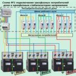
- Scheme number 1
-
- Scheme No. 2
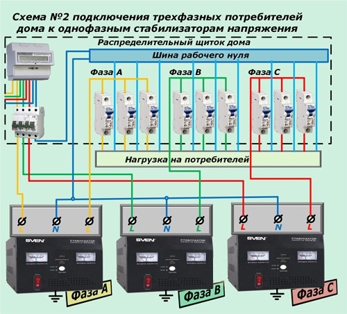
In domestic conditions, three-phase power consumers are connected through a single-phase device.
Checking the assembled circuit
The first start is carried out without applying a load. Only the introductory machine is involved, the rest are turned off.
You need to start idling and see how everything works.The output and input parameters are checked, the absence of extraneous sounds and noises. It is recommended to see what data is displayed on the scoreboard.
If everything is correct, power can be supplied.
Main mistakes
The most common connection errors include:
- Wrong location choice. You can understand that the place was chosen poorly by overheating the device, turning it off, and the appearance of erroneous information on the scoreboard.
- Using a regular machine, not a three-position. Using a classic circuit breaker will not protect the device from damage. The voltage regulator must go from normal to “transit” with a certain sequence. First, the automatic devices on the panel are turned off, then the switch is switched to the "transit" mode. Only after that the machines are again activated. If you do not follow the above sequence, switching will be carried out under load, because of which the equipment fails. When using the three-position switch, it is not necessary to memorize the algorithm.
- Incorrect connection of the voltage regulator for the house, the connection diagram is selected incorrectly.
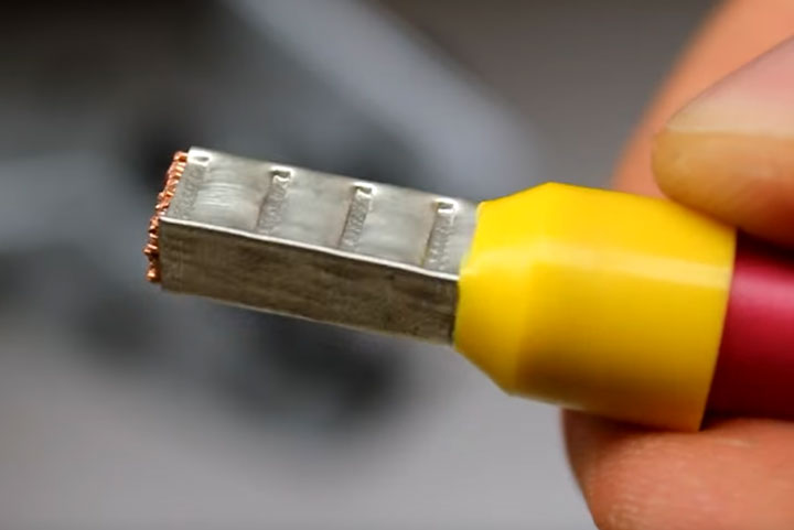
 Lack of tips on multicore wires
 - Wrong choice of cable cross-section. A thinner wire is not able to withstand all the load suitable through it, which leads to damage to the devices.
- Not using tips. All wires must be crimped, even when connecting devices with a small amperage.
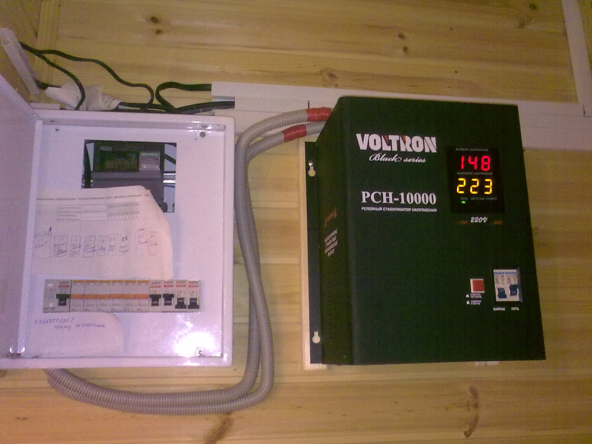
- Problems with machine guns in the shield. Even with the correct connection and proper functioning of the device, knockouts can occur. It can be caused by a low supply voltage (for example, 150-160 V at the required 220-230 V).
When installing the device, you must take into account all the nuances and not make the listed errors.