To equip the electricity supply, draft drawings are needed. To understand the drawing and read it, you need to know the legend. The circuit breaker in the diagram is indicated in different ways, which often leads to misunderstandings, errors in the assembly of electrical panels and wiring.
Symbols of electrical elements and types of circuits
The initial question that every electrician usually faces is the design documentation for a room or facility that needs to be electrified. Before proceeding with the installation of equipment, a qualified specialist should familiarize themselves with the accompanying documents.
Equipment and elements in the diagram can be indicated by both alphabetic and graphic images. Drawings are developed in accordance with GOSTs and the rules for marking equipment and elements in drawings and plans. A detailed description and requirements for electrical circuits are given in GOST 2.702-2011 ESKD. In addition to graphic and letter designations, diagrams are affixed with nominal sizes.
There are many types of different schemes. In electrics, three main types are most often used. Functional display the main nodes of the device, without detailed detail. They look like a set of separate blocks, interconnected in a certain way. The scheme gives a general idea of the operation of the object.
The circuit diagram contains detailed instructions for each element, its contacts and communications. It can describe both a standalone device and an electrical network. On single-line diagrams indicate power circuits. The control method and control are described on a separate sheet. If the device is not complicated, everything is placed on one document.
On the wiring diagrams indicate the elements and their exact location. If this is the wiring in the apartment or house, indicate the place of installation of switches, lamps, sockets. Also affix distances and ratings. Indicate the position of the parts, the order and method of their connection.
The residual current circuit breaker (RCD) and the difavtomat in the diagram do not have a specific geometric shape. For their graphical execution, an image of blocks and dynamic blocks is used. Each device in the diagram is assigned an alphabetic marking and a position number is indicated.
In addition, the parameters of the elements that are in the drawing are applied. They paint the basic data about the element so as not to make a mistake during installation and choose the appropriate device. These symbols are used to draw drawings of power supply, power equipment and electric lighting. And also in the basic single-line circuit diagram of electrical panels.
Circuit breaker designation in the diagram
The graphic designation of the machine in the diagram is due to GOST 2.755-87 ESKD, alphanumeric - GOST 2.710-81 ESKD. There are no special requirements for marking, so electricians often use their own values and labels. You can find documentation when the definition of the switching apparatus differs in different projects.
Each designer, performing the scheme, can depict an RCD at its discretion. It is enough to indicate in the explanations to the scheme UGO (conventional graphic symbols) and their decoding.
Depending on the characteristics of the device, the elements have different alphabetic characters, as well as the following graphic symbols on electrical diagrams.
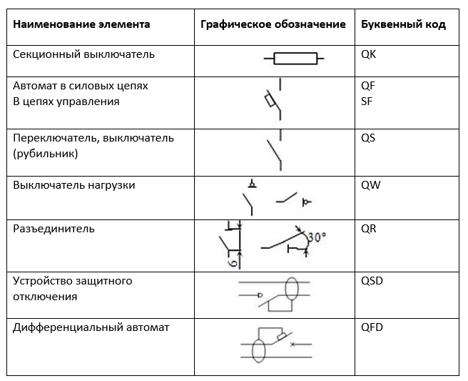
Circuit breakers are recommended to be positioned as, QF1, QF2, QF3. Switch disconnectors - QS1, QS2, QS3. The fuses in the diagrams show as FU with a serial number, where the encoding of the letter Q stands for a circuit breaker or circuit breaker, and F is protective. This combination is quite applicable not only to ordinary automata, but can also be a designation of a differential automaton in the diagram.
For RCDs, a combination of QSD is used, the designation of the differential automaton in the diagram looks like QFD.
RCD designation on a single-line diagram
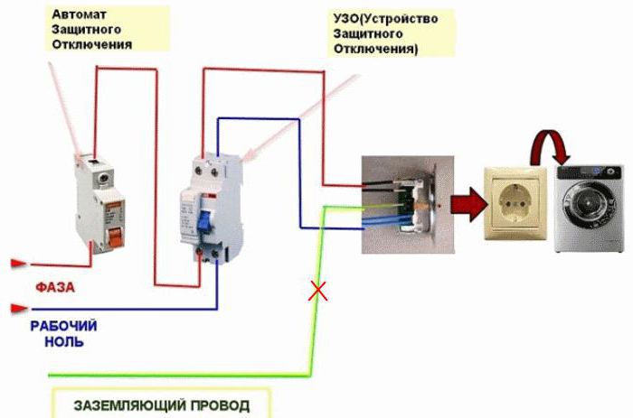
This is a type of shutdown device, the function of which is to disconnect the network or part of it when a certain differential current mark is exceeded. The device improves electrical safety, prevents emergencies, both in the manufacturing sector and at home. The RCD connection diagram is simple, but installation flaws can lead to serious troubles.
So you can designate an RCD on a circuit diagram.
RCDs together with other elements in the project documentation are most often performed conditionally, which makes it difficult to decipher the principle of operation of both the entire circuit and individual elements. The image of the protective device may look like a normal switch. But on a non-linear circuit, it is two parallel switches. On a single-line - elements, wires and poles are represented symbolically.
Any schematic image must be correctly composed, and later read. The smallest flaw can lead to a malfunction of the RCD or the entire system. It is important to consider the following common errors:
- Zero and ground are connected after the protective device. If the circuit is not correctly interpreted, the neutral can be connected to the open part of the installation or to a neutral protective conductor.
- If the device is connected out of phase, a false alarm occurs.
- Incorrect connection of conductors in sockets leads to the device tripping even if nothing is included in the socket.
- The connection of the neutral conductors of two machines leads to uncontrolled shutdowns.
- A common mistake is when phases and zeros related to different devices are mixed up.
- Non-observance of polarity leads to the movement of currents in one direction. Before installation, you should carefully familiarize yourself with the location of the terminals.
A preliminary scheme is always carried out, taking into account possible errors occurring in the network. If the document is composed correctly, the operation of the security device is effective.
It is important to remember safety precautions. It is necessary to periodically inspect the wires, in case of damage to them, the RCD is triggered and the power supply stops. Therefore, it is better not to delay repair.
Real Project Example
A single-line circuit diagram (OPS) is nothing more than a drawing of a plan, for example, an apartment. It should indicate the distribution groups. To do this, you need to measure all the walls and execute the drawing in compliance with the scale. It will take several copies to display a separate group on each.
Distribution groups are points that will be connected to one machine of the apartment panel. All wiring cannot be connected to the same group. Otherwise, you need a powerful cable that will be able to withstand the load of all devices.
Depending on the number of rooms and the availability of energy-consuming devices, distribution groups may look as follows.
- lighting of the room, hallway and kitchen;
- lights and sockets in the toilet;
- sockets in the living room;
- outlets in the hallway and kitchen;
- electric stove.
It is recommended that rooms with high humidity be connected as a separate group, for which an RCD is required.If the apartment has small children, a protective device is connected to each group.
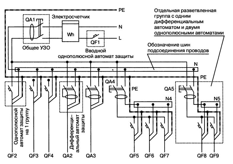
A basic, or single-line diagram is necessary for the correct connection of switchboard and distribution groups.
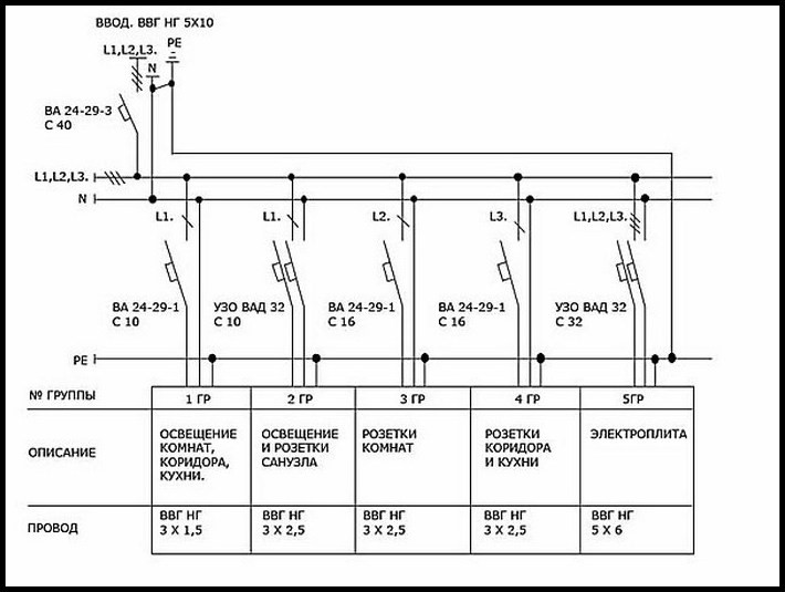
This example shows the connection to a three-phase power supply. The entire apartment is fed by an input cable of 5 cores, a cross section of 10 mm2. The phases are numbered as L1, L2, L3, grounding is PE, which closes with zero. Introductory automaton (VA) disables all automata of groups that are marked in the same way.
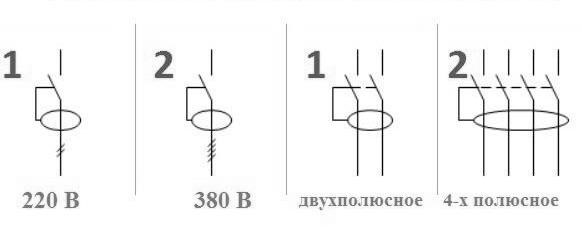
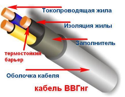 The number of phases is determined by the number of dashes in the diagram. Single-phase - \, or three-phase - \. The marking of the VVG NG wire indicates that it is with non-burning insulation, three-core with a cross section of 1.5 mm2.
The drawing makes it possible to determine the number and brand of the necessary protective devices. Count the number of switches and sockets, as well as how many meters of cable you need.
All wire connections must be in junction boxes. A separate box is recommended for each room. If, for example, a gas boiler and other electrical appliances are located in the kitchen, two junction boxes are required.
There are no special requirements for the installation of sockets and switches. They are installed so that it is convenient. In the kitchen and workplace, sockets are placed above the table.
Stationary household appliances, boilers, hoods, a towel dryer are connected immediately through the terminal blocks. The Internet and television outlets can be combined with electrical.
Designation of a differential automaton in the diagram
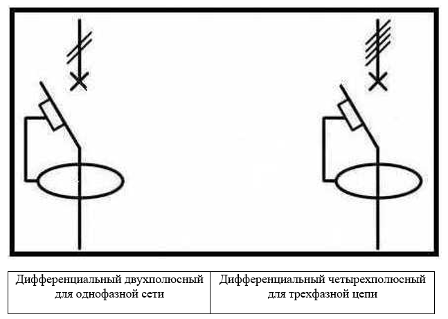
The differential machine combines in one device a residual current device and a circuit breaker, which is what distinguishes it from RCDs. In this case, the graphic image on the diagram is as follows.
If for RCDs the alphanumeric designations Q1 are accepted, then for AEDT (residual current circuit breaker) - QF1. The letters indicate the functions of the device, and the numbers indicate its serial number in the circuit. Another letter combination is QF1D, where D stands for "differential".
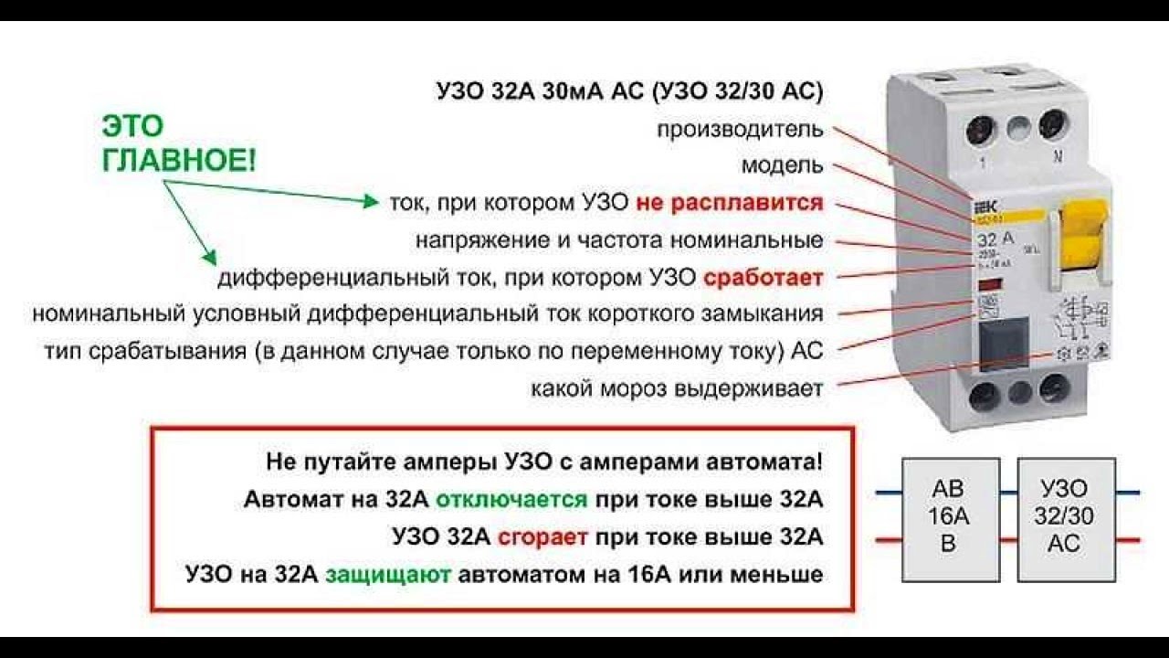
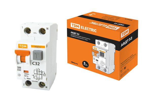
The main characteristic of such devices is the rated operating current at which the machine remains on for a long time. These indicators are strictly standardized, and the current may have values: 6 Amps; 10; sixteen; 25; 50 etc.
Another important characteristic is speed. The current indicator is indicated by the letters B, C, D, facing the value of the rated current. For example, the combination C16, says that the automatic speed controller C is designed for a rated current of 16 Amps.
The differential allowable indicator fits into the following row: 10; thirty; 100; 500 milliamps. On the body of the device is indicated by a "delta" with a number corresponding to the leakage current.
The operational capabilities of the machine are designed for a rated voltage of 220 volts for a single-phase circuit and 380 for a three-phase circuit.
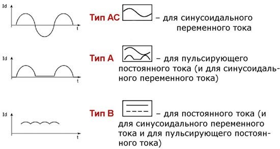
Difavtomats are distinguished by type, depending on the leakage current, and are marked with the following letter indices:
- A - reacting to leakage of alternating or constant pulsating current;
- AC - designed to respond to leakage with a constant component;
- B - type of device, including both of the previous features.
This characteristic can be marked with a small drawing indicating the type of current.
The devices operate on a selective basis, have the ability to delay the response time. This ensures selective disconnection of the device from the network and the stability of the protection system. This characteristic is indicated by the letter S and gives a delay of 200-300 milliseconds. Marking G corresponds to 60–80 milliseconds.
Since the starting currents exceed the operating value, the protection is designed so that an electromagnetic shunt trip releases the device when the current is several times the nominal size.
Regulatory documents contain many special ciphers and signs.Most of them are practically not used in everyday life. For the correct reading of the electrical circuit, you need to know the basic notation and take into account some nuances. One of them is the country producing equipment, cables or wiring, since there is a difference in the marking and legend, which makes it difficult to correctly interpret the drawing.