Self-development of the project and installation of wiring is a rather troublesome business, although quite feasible on its own. In this case, the design and installation of electrical wiring will require the owner of the house to have special knowledge and experience in carrying out such work. If there are no such skills, it is better to use the services of qualified specialists.
General design rules
The electrical wiring of a private house is a combination of cables and wires laid inside the building, complete with protective, installation and mounting elements. As a rule, they are laying it in accordance with a project agreed and approved in the established order and carried out by a specialized company with the appropriate license. Before the development of the familiarization of designers with the layout of the building and a conversation with its owner. During a conversation, it is determined:
- the number and lifestyle of people living in the house;
- in what quality will the house be used (main or seasonal housing);
- estimated composition of energy-consuming equipment.
The main requirements that apply to the wiring of a private house are safety and reliability. As a rule, a transformer substation serves as a source of electricity for buildings of this type, the voltage from which is supplied to the consumer via an overhead power line or an underground electric cable. Therefore, at the first stage of design, the owner of the house must accurately calculate the amount of energy consumption. The choice of wires, cables, as well as protective and switching devices depends on this value.
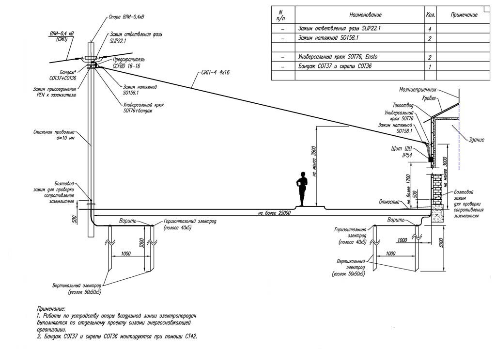
Before starting work on the design of wiring, the owner of the house must conclude an agreement on its power supply. After that, the power supply company will carry out a tap from the nearest main power line and install an opening machine and a meter on one of the exterior walls of the house. She will provide further their connection.
The design of electrical wiring in a private house should be subject to the requirements specified in the current regulatory and technical documentation (PUE, VSN, SNiP, etc.):
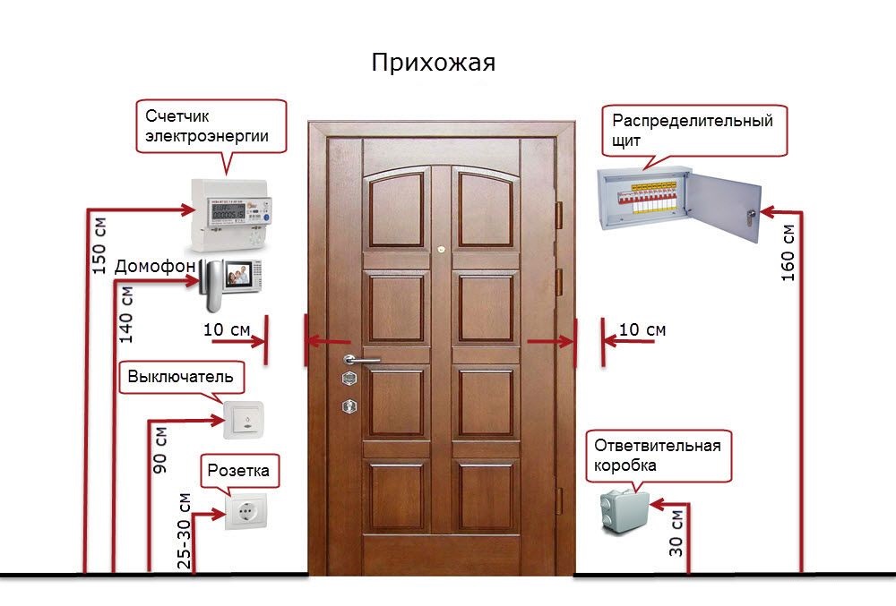
- Switchboard with protective device should be installed at a height of 150-170 cm from the floor.
- Electric wires and cables are laid parallel or perpendicular to the floor surface.
- The cables and wires from the distribution, protective and switching devices must be taped at an angle of 90 °.
- Turning / bending of cables and wires during installation should be carried out at a right (90 °) angle. Diagonal placement of cables and wires during wiring is prohibited.
- From the door and window openings, the laid wires and cables must be removed by at least 15 cm.
- Outlet blocks should be located at a height of 30-40 cm from the floor surface.
- Switches should be installed at a height of 80-90 cm from the floor, while the distance to the doorways cannot be less than 15-20 cm.
When designing a wiring diagram, the owner of the house should not forget about comfort. Near double beds, you can provide electrical outlets on both sides, and in the kitchen to install power outlets in the area where the kitchen equipment is located.
Wiring diagram
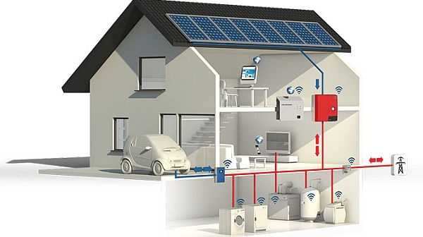
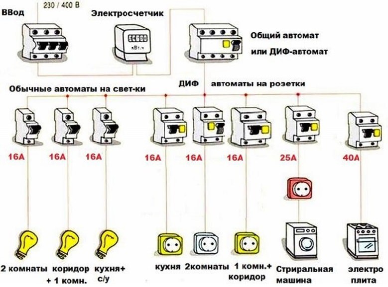
A modern private house is equipped with a large number of various electrical appliances, among them there are also quite powerful ones. This imposes certain requirements for the selection of cable products, protection devices and other necessary equipment. It is recommended that electrical wiring be divided into a number of circuits, connecting each of them to a separate protection device (circuit breaker).
Wiring design begins with the development of a wiring diagram. In this case, it is desirable to at least roughly imagine where the main consumers of electricity will be located (washing machine, microwave oven, water heater, etc.), which in turn will allow for the location of sockets in the immediate vicinity of these devices.
Having drawn a sketch of the wiring of the electrical wiring, the owner of the house can easily:
- calculate the maximum electrical load for each room;
- calculate the total power consumption;
- make a list of necessary materials and components;
- select the cross section of wires and cables.
Wiring Type Selection

The electrical wiring in a private house can be performed in two ways - external (open) or hidden.
The external method of laying wires is used in wooden houses or when decorating the interior of a house in the "Retro" style. In this case, the project should provide for the laying of wires in plastic boxes or with fastening on porcelain insulators. The latter will require the use of a special cable. You will also need sockets and switches made in the outdoor version.
When installing the cable externally in the diagram, in addition to the route of its wiring, you will also need to indicate the installation locations of the insulators.
In modern buildings, as a rule, they use a hidden method of wiring. It is somewhat more complicated, since the owner will have to do the strobes in the walls, where the cable will then be laid. The laid wires will then have to be fixed with alabaster or gypsum mortar. Sockets and switches must be of internal design. For them, the project should provide for the installation of special sockets.
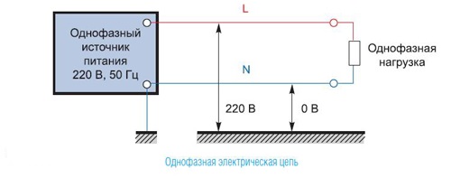
Getting to the design of electrical wiring, you need to determine the type of connection of the house to the electrical network - it can be single-phase or three-phase. If it is possible to connect the house to a three-phase network (~ 380 V), it is better to use it, since most powerful household appliances are designed to connect to such an electrical network. Their operation from a single-phase network is considered only as a compromise option. If there is no possibility of connecting to a three-phase network, only one option remains - a single-phase network ~ 220 V.
-
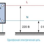
- Single phase mains
-
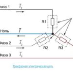
- Three Phase Power
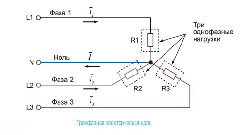
The presence of a three-phase input will require taking care of the uniform load of each phase, otherwise, with poor contact or complete burn-out of “0”, the voltage on the phase wires will begin to differ from each other. At the same time, due to the increased (~ 250 ... 280 V) or lower (~ 180 ... 150 V) voltage, household appliances operating at the single-phase supply level of ~ 220 V may fail. The energy consumption of devices insensitive to such a voltage imbalance will increase significantly. To avoid these negative phenomena, it is necessary to distribute electrical appliances into groups so that the load on the network and each phase separately is optimal.
Calculation of power consumption

The development of a wiring project is impossible without determining the total power consumption. It is determined by summing up the power consumption of all electrical appliances that are supposed to be used in a house, garage, basement, workshop and in a personal plot.Then, the obtained value is multiplied by the coefficient of simultaneity of switching on the devices, which is usually taken equal to 0.7.
Then proceed to the distribution of electrical appliances into groups, based on the fact that the total power consumption of one group should not exceed 4.5 kW.
Consumer groups
Given the large number of the most diverse electrical appliances that are operated in the house, it is better to divide cable lines into several groups:
- outlet (low-power household appliances);
- lighting;
- Separate power lines for household appliances such as electric stoves, water heaters, washing machines, air conditioners, etc.
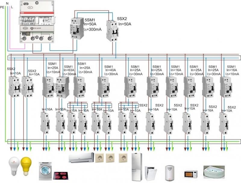
According to the requirements of the BCH 59-88 (paragraph 7.2), sockets installed in the kitchen and in living rooms must belong to different groups. At the same time, the rated power of the circuit breakers of these group lines should not exceed 16 A (paragraph 9.6).
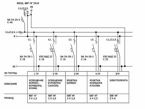
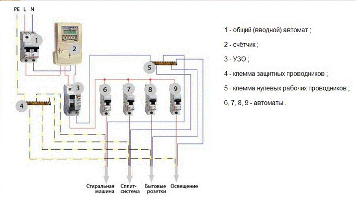
The first group includes general lighting devices connected to phase L1 through a 10 amp circuit breaker with a leakage current of 10 mA. The second group includes energy consumers installed in the bathroom and toilet. Given the high humidity of these rooms, electrical appliances of this group are connected to phase L1 through a residual current device (RCD) with a rated leakage current of 30 mA (PUE requirement). Power supply to indoor outlets (third group) and outlets installed in the kitchen and corridor (fourth group) is supplied from phase wires L2 and L3 through 16 amperes. The electric stove (fifth group) is connected to a three-phase network (L1, L2, L3, neutral wire + ground) through an RCD designed for a current of 32A.
Guidelines for choosing wires
The selection of cables and wires, as well as the calculation of the cross section of their conductive conductors, is one of the main stages in the design of electrical wiring. Missing switches and sockets can be installed later, incorrectly selected machines can be easily replaced, but removing wires from the walls is not easy. The durability and reliability of the wiring depend on the calculation made correctly. Ensuring fire safety is equally important.
When choosing the brand of wires, it is necessary to take into account the requirements of PUE 7 “Rules for the installation of electrical installations”.
- In residential buildings, only wires and cables with copper conductive cores are used (Section 7.1.34). In this case, the lines of group networks should have a cross section of at least 1.5 mm, and the lines going to the current meter should have a minimum of 2.5 mm.
- All lines laid from group panels to outlets and general lighting fixtures must be three-wire - phase L, zero working N, zero protective PE (paragraph 7.1.36).
There are several methods for calculating the cross section of conductive conductors. Their diameter is calculated by the following indicators:
- power consumed by all consumers;
- total current value;
- necessary length of the laid line.
However, you can omit all these calculations, and determine the cross section of the conductive conductors based on the nominal parameters of the group machines. In this case, the laying method must also be taken into account, since the heat transfer of wires laid in an open or closed way is different.
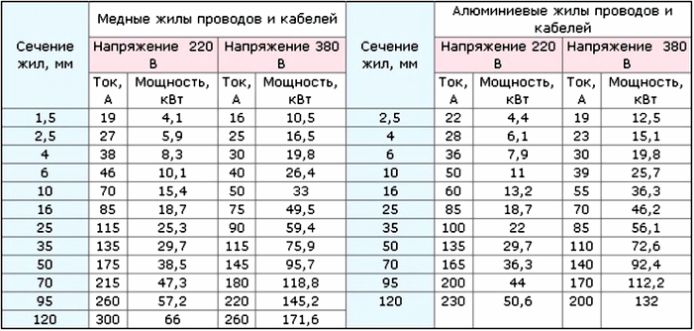
In the general case, the required cross-section of conductive conductors can be selected using table 1.3.4 (clause 1.3.10 of PUE 7). However, for lines of high-power devices, the cross-section of conductive conductors is still desirable to calculate separately.
When determining the brands of wires for electrical wiring, it is better to lay cable products in the project. The cable is distinguished from wires by improved insulation, which makes it safer to use. As a rule, non-combustible cables such as VVGNG or VVGNG-LS are used for wiring inside the house.
Designing and approving a project
The presence of an individual wiring project for a private house is required in such cases:
- electrical wiring in the building is mounted for the first time;
- large-scale reconstruction of the house is planned with a change in the existing wiring diagram and the installation sites of powerful electrical equipment;
- a significant increase in power consumption is needed.
For private property, in which the total power consumption is less than 10 kW - it is allowed to develop a simplified drawing design of the wiring; more than 10 kW - it is necessary to develop a full-fledged electrical project.
The development of project documentation is started after receiving technical specifications (TU) from the organization that contains the power line on the balance sheet, from which it is supposed to receive electricity. For the project developer, the implementation of the requirements and recommendations set forth in the technical specifications are mandatory.
The developed project documentation should be agreed with the organization that issued the technical specifications and the local state energy supervision authority.
Drawing project of laying electrical wiring and a set of documents
In the general case, the drawing project must, along with the scheme of external and internal power supply, contain reliable data on such factors:
- type and place of installation of circuit breakers;
- marks and sections of used wires and cables;
- value of the calculated current load;
- electricity metering devices;
- The method of connecting wiring to the mains.
In addition, the documentation should include:
- situational layout of electrical equipment, laying of cable products, as well as grounding and grounding conductors;
- lists of necessary materials, components and electrical equipment;
- explanatory note (if necessary).
A full set of design documentation is being developed for a private house in which the total electrical power of electrical equipment exceeds 10 kW. Must contain:
- external and internal energy supply schemes;
- internal wiring diagram indicating the brands of cable products and the way they are laid;
- input device circuitry;
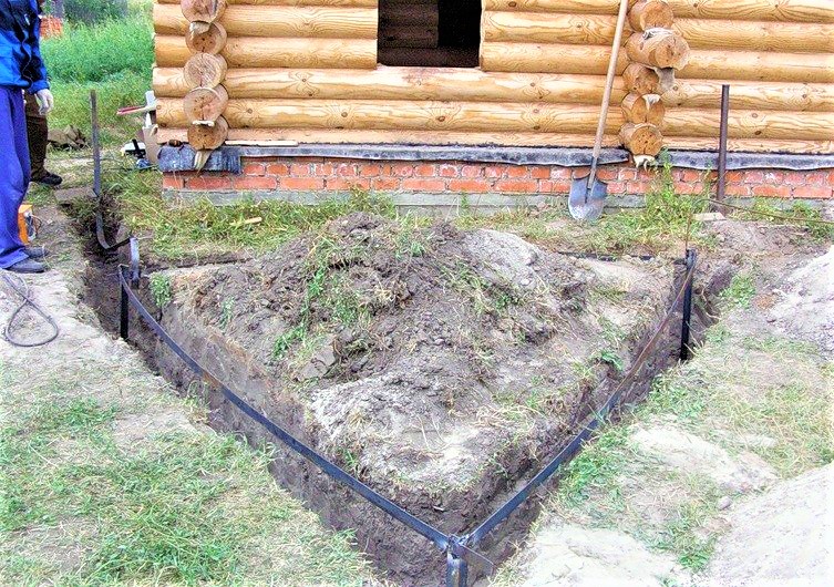
- grounding and / or grounding scheme (if necessary);
- calculation of electrical loads;
- calculations confirming the correctness of the selected machines and RCDs;
- electricity metering calculation.
You can clarify information about documents in the energy supplying organization.
Typical wiring diagrams
When developing design documentation for electrical wiring for a private house, designers recommend using standard wiring diagrams for different types of rooms. All these circuits have the same structure, which is based on dividing the wiring into a number of circuits, with each of them connected to a separate machine.
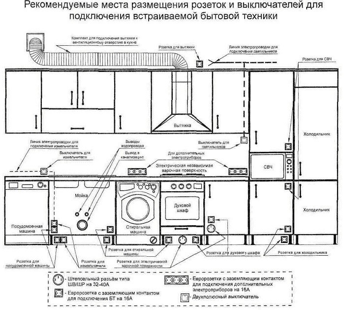
Wiring diagram in the kitchen
The peculiarity of the electrical wiring in the kitchen room is characterized by the presence of a large number of fairly powerful electrical appliances, for which it is advisable to separate lines with their circuit breakers. The main task of the designer in this case is the optimal location of the outlets - they must be placed next to electrical appliances, providing for the possibility of free access to them for repair or for rearrangement / shutdown of household appliances. In this case, not only the location of electrical appliances, but also the arrangement of kitchen furniture should be displayed on the diagram.
Garage / basement wiring diagram
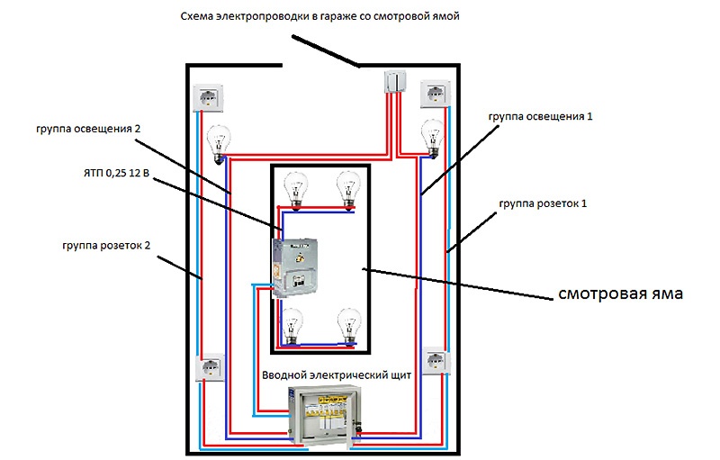 Starting to develop a wiring diagram in the garage, you need to determine the number of sockets, switches and sockets and specify their location.For example, sockets are best installed at a height of 1 m, and switches - at a height of 1.5 m from the floor. Junction boxes are usually placed under the ceiling at a distance of no more than 20 cm from it.
Quite often, the owner also uses the garage as a workshop. Therefore, when wiring, it is necessary to provide the ability to connect a power tool, compressor, or even metal or woodworking machines. This is only possible with a three-phase power supply. Depending on which network is installed in the garage, the wiring diagram also depends. At the same time, on the switchboard, machines should be installed for each group of wires and RCDs.
Given the high humidity in the basement and the inspection pit of the garage, experts recommend using safe lamps rated for 12 V when organizing the lighting. To connect the wiring leading to such lamps, you need a step-down transformer.
The general plan of the electrical wiring in the house
In some cases, before the wiring diagram is drawn up, it is recommended to develop a preliminary diagram listing all the devices intended for installation in the house. Such a scheme will facilitate the calculation of the total number of lines to the switchboard and the total number of circuit breakers and RCDs. It also indicates the type of supply network, which allows you to select the appropriate cable, type of protection device and model of the meter.
The explanatory note to the plan indicates that the input device and the electric meter are installed on one of the external walls of the house, and the general distribution electric panel is located in the corridor or in some separate room, for example, in a nearby garage. In order not to create difficulties for maintenance later, in houses with 2 or 3 floors, it is recommended to provide intermediate distribution switchboards connected to a common switchboard on each of them.
In a similar way, an electrician plan is developed for a small one-story house.
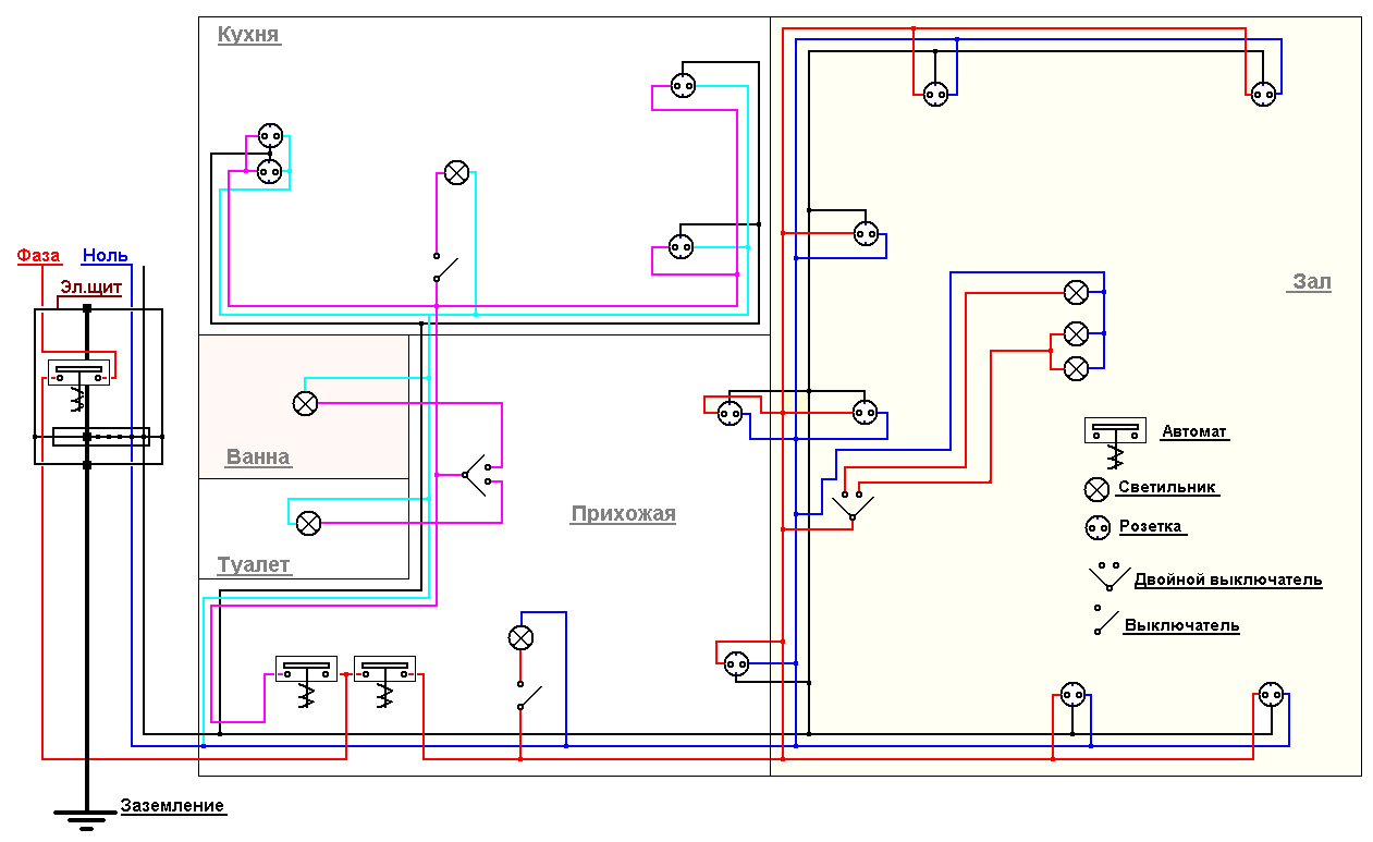
Wiring diagram
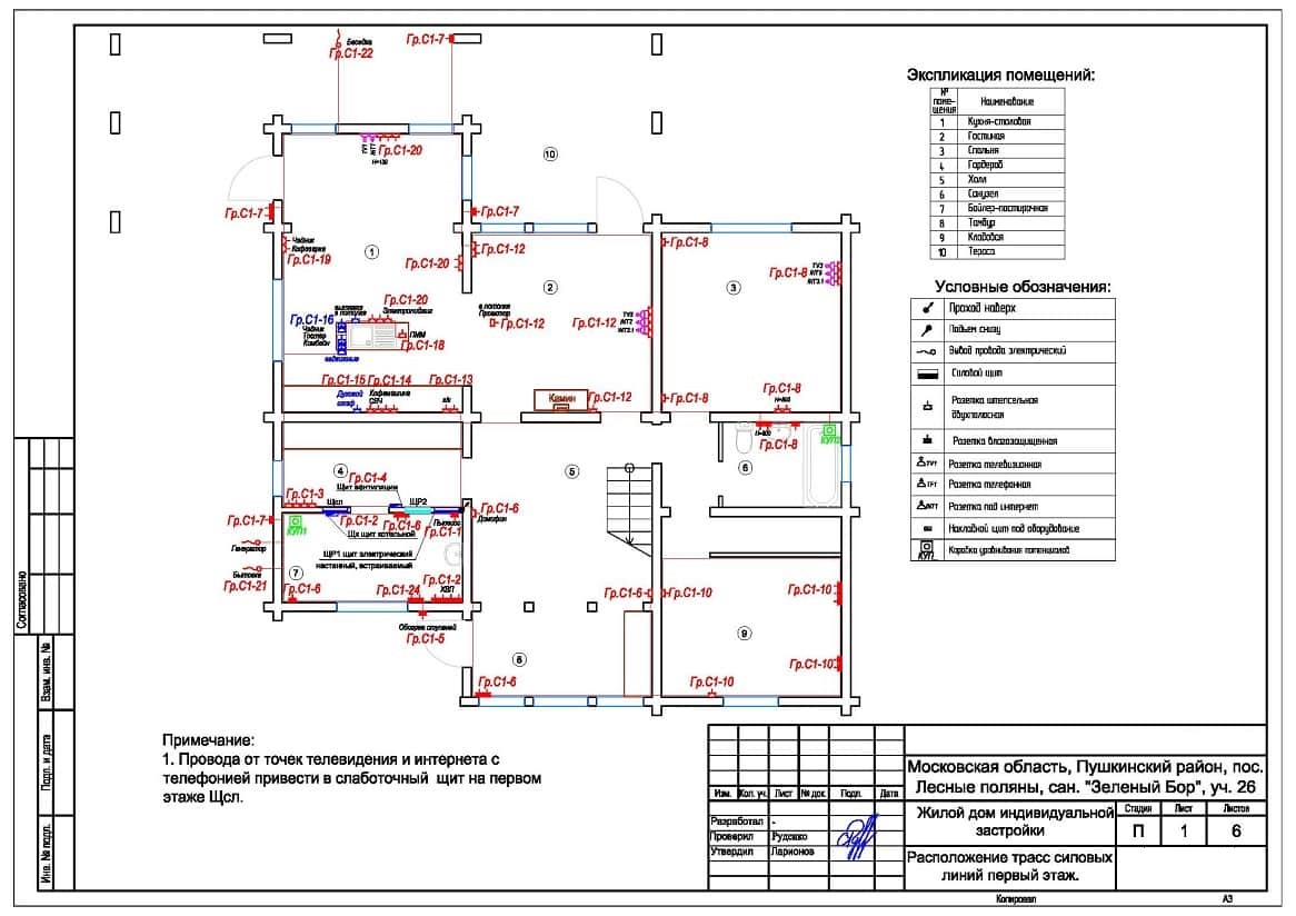
Based on pre-compiled plans, it is possible to develop a general wiring diagram for electrical wiring, using which it is easy to calculate the required number of switches and sockets and additional equipment and materials, as well as the footage of cable and wire products.
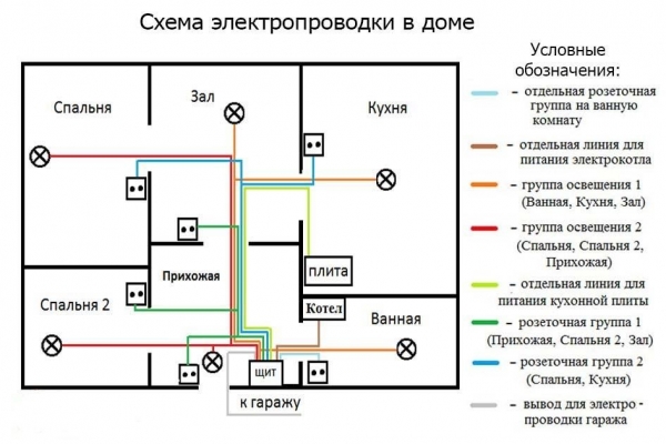
Develop a wiring diagram using a copy of the house plan, which indicate:
- power line entry point;
- places of installation of the electrical panel, junction boxes, electrical appliances, sockets, switches and lighting lamps.
If it is planned to install electrical appliances of increased power in the house, they also need to be shown on the diagram, since the power for them must be supplied through separate lines.
If the design of a private house provides for detached farm buildings, the wiring in them also needs to be displayed on the wiring diagram.
To facilitate the calculation of the required number of cables and wires, the connecting lines of each circuit should be painted in different colors.
It is also recommended that conductive conductors of the same cross section be marked on the plan with one color. This will simplify the determination of the range of necessary cable products and simplify the process of laying them.
Common Design Errors

The desire for savings often forces owners of newly constructed or reconstructed private houses to independently develop a wiring project. However, behind the seeming simplicity of this work, there are a sufficient number of problems, ignoring which leads to errors that can disrupt the regular operation of the home electrical network.In this case, the residents may be affected by electric shock, and in some cases, a fire in the electrical wiring.
When designing the wiring diagram in a private house, the contractor should avoid repeating common mistakes:
- the use of materials and components without marking, often not certified for use in the country;
- the use of cable products with conductive wires of aluminum;
- inclusion in the estimate of the project of sockets not intended for connecting electric stoves, electric boilers, water heaters, etc .;
- introducing the laying of wires in a closed way into the wiring project of a wooden house;
- switching power cables in one junction box with low-power lines;
- use of twisted wires instead of special terminals;
- the location of junction boxes at the height of human growth.
It is forbidden to ground electrical appliances on metal pipes: sewer, gas, water, etc.