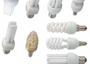
In the electrical circuit of a car, a voltage regulator of 12 volts is often used. The need to install it is explained by the fact that automotive power sources (battery and generator) of various 12-volt electrical appliances give direct current with a voltage of 12.5 to 14 V. Such large fluctuations can lead to damage and failure of sensitive and expensive LED tapes, fog lights, radio. Also, in addition to the electrical systems of automobiles, such devices are used in 12-volt power supplies capable of lowering and converting the alternating current of an electric household network to a constant one, which is more suitable for a number of devices.
Device selection
When choosing a stabilizer take into account the following characteristics:
- Sizes. The selected stabilizer should be compactly located in the intended place for installation with normal access.
- View. Of the commercially available devices, the most reliable, compact and inexpensive are stabilizers based on small microcircuits.
- The possibility of self-repair. Since even the most reliable devices fail, it is necessary to give preference to maintainable stabilizers, radio components for which are commercially available in sufficient quantity and at an affordable price.
- Reliability. The selected stabilizer should provide a constant voltage value without significant deviations from the range declared by their manufacturer.
- Cost. For the electrical system of the car, it is enough to purchase a device worth up to 200 rubles.
Also, when choosing a stabilizer, it is necessary to take into account the reviews of their customers, which can be found on specialized forums and sites.
Varieties of 12V stabilizers
Depending on the design and method of maintaining 12-volt voltage, two types of stabilizers are distinguished:
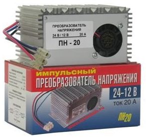
- Pulse - stabilizers, consisting of an integrator (battery, high-capacity electrolytic capacitor) and a key (transistor). The voltage is maintained in a given range of values due to the cyclic process of accumulation and fast charge transfer by the integrator when the key is open. By design features and control method, such stabilizers are divided into key devices with Schmitt trigger, equalizers with pulse-width and pulse-frequency modulation.
- Linear - voltage-stabilizing devices in which zener diodes connected in series or special microcircuits are used as a regulating device.
The most common and popular among car enthusiasts are linear devices characterized by the simplicity of self-assembly, reliability and durability. Pulse mode is used much less often due to the high cost of parts and the difficulties of self-manufacturing and repair.
Classic model
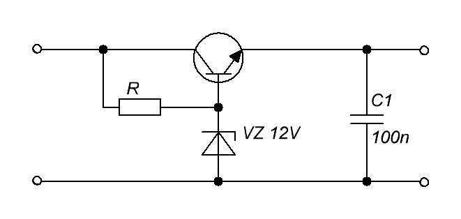
Classical stabilizers are a large class of devices assembled on the basis of such semiconductor components as bipolar transistors and zener diodes. Among them, the main function of maintaining the voltage at 12 V is performed by zener diodes - a kind of diodes connected in reverse polarity (plus a power source is connected to the cathode of such a semiconductor device, and minus is connected to the anode), operating in the breakdown mode. The essence of the work of these semiconductor parts is as follows:
- When the voltage of the power source connected to the zener diode is less than 12 V, it is in the closed position and does not participate in the adjustment of this characteristic of the electric current.
- When the threshold of 12 volts is exceeded, the zener diode “opens” and maintains this value in the range specified by its characteristics.
In the case of excess voltage supplied to the zener diode, relative to the declared maximum manufacturer, the device very quickly fails due to the effect of thermal breakdown.
In order for any zener diode model to serve as long as possible, it is recommended that its specification specify the voltage range, current strength in which it should be operated.
Depending on the connection, two versions of the classical stabilizer are distinguished: linear - control elements are connected in series to the load; parallel - voltage-stabilizing devices are parallel to powered devices.
Integral stabilizer
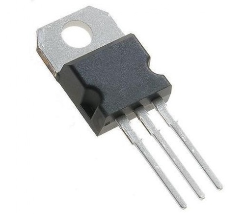
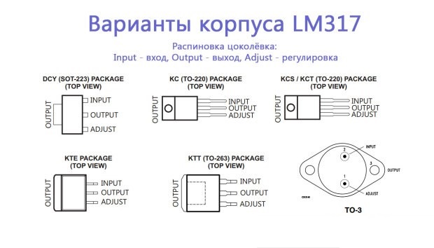
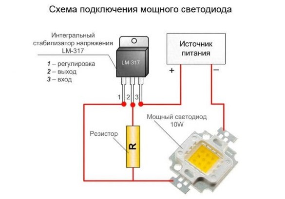 The devices are assembled using small-sized microcircuits capable of operating at an input voltage of up to 26-30 V, producing a constant 12-volt current of up to 1 Ampere. A feature of these radio components is the presence of 3 legs - “input”, “output” and “adjustment”. The latter is used to connect an adjustment resistor, which is used to configure the chip and prevent its overloads.
More convenient and reliable equalizers assembled on the basis of stabilizing microcircuits gradually displace analogs assembled on discrete elements.
How to make a 12V stabilizer
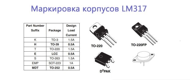
Simple, but at the same time quite effective, reliable and durable stabilizing devices can be made independently, using simple zener diodes and special small microcircuits like LM317, LD1084, L7812, КРЕН (КР142ЕН8Б).
Stabilizer on the LM317
 The assembly process of such a voltage stabilizing device consists of the following steps:
- A 130-ohm resistance is soldered to the average output pin of the microcircuit.
- A conductor is soldered to the input right contact, supplying unstabilized voltage from the power source.
- The left adjustment contact is soldered to the second leg of the resistor installed at the output of the microcircuit.
 The process of soldering such a stabilizer takes no more than 10 minutes and, taking into account an inexpensive microcircuit, does not require large investments. With the help of such a device, LED lights, ribbons are fed.
Integrated circuit LD1084
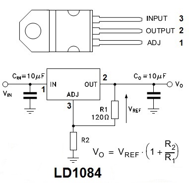
The assembly of the device for stabilizing the voltage of an automotive electrical system using the LD1084 chip is as follows:
- A conductor with a positive voltage from the diode bridge is soldered to the input contact of the microcircuit.
- An emitter of a bipolar transistor is soldered to the control contact, the base of which feeds the low and high beam current through two resistors with a nominal value of 1 kOhm.
- Two resistors are soldered to the output contact (one is normal at 120 Ohms, and the second is trimmer at 4.7 ohms) and an electrolytic capacitor at 10 uF
To smooth the current ripple after the diode bridge, another electrolytic capacitor with a capacity of 10 microfarads is installed.
Stabilizer on the diodes and the board L7812
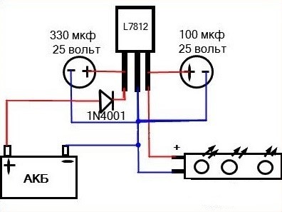
A simple integrated equalizer on a Schottky diode and two capacitors is assembled as follows:
- The following contact is soldered to the input contact of the microcircuit: a diode of the type 1N4007, the anode of which is connected to the plus of the power source using a wire, and the positive lining of a powerful 16-volt electrolytic capacitor with a capacity of 330 μF.
- The load and the leg of the plus plate of a 16-volt electrolytic capacitor at 100 μF are soldered to the right output contact.
- The minus, coming from the battery, and the wire from the minus plates of the capacitors are soldered to the middle adjustment contact.
From such a simple device, you can power powerful tapes of LEDs and a radio tape recorder.
The easiest stabilizer is the ROLL board
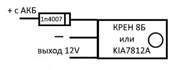
The voltage regulator circuit for 12 volts based on the roll board (KR142EN8B) includes the following components:
- A rectifier diode type 1N4007 soldered to the input terminal.
- Chip KR142EN8B or KIA7812A.
- Two wires soldered to the output and control contact of the microcircuit and connected to the load and minus the power source.
The design on the KREN board is the easiest and fastest to assemble. At the same time, its effectiveness and scope are the same as for other home-made analogues.