Modern household equipment (washing machines or microwave ovens, for example) are necessarily equipped with built-in timers. In addition, the devices are installed in single-line power supply schemes and perform the function of controlling the operation of the load, turning it on or off at the right time. To make a home time relay yourself, you need to study the design features and the principle of their action.
Principle of work and scope
The simplest example to understand the principle of relay operation is a mechanical or electronic alarm clock set up for a certain time. To get a full-fledged timer, an executive device is added to it, which performs the necessary function - supplying power to the chandelier or fan, for example. The order of operation of such a relay:
- As soon as the time interval set on the timer (hours) has expired, the control signal enters the relay coil.
- Immediately after this, its working contacts open or close the supply circuit.
- As a result, the device connected to it is turned off or on.
In real devices, this mode of operation is implemented taking into account a predetermined time delay.
Timers of various types are widely used to control the functioning of industrial plants, as well as when turning on and off household appliances. The following are commonly used as switched household loads:
- lighting devices of any class;
- various samples of climatic equipment;
- ventilation systems and similar devices.
The use of household appliances with time management allows you to reduce the cost of paying for electricity.
Before you make a timer for turning on and off electric appliances with your own hands, you will need to familiarize yourself with the varieties of these devices.
Types of Relays
According to the type of output element used in the switching circuit, known time relay samples are divided into the following types:
- relay systems, the main switching element of which is a working contact;
- transistor switches on key semiconductor elements;
- triac or thyristor switches.
The first of the options is not very suitable for independent manufacture, since its layout is relatively complex - it contains too many elements.
It is recommended to choose a thyristor circuit solution when the connected load is insensitive to the form of the supply voltage.
In homemade products, it is unreasonable to use modern microcontrollers, which significantly complicate the process of setting up and adjusting the executive part of the circuit. More preferred are transistor relays, which are easy to assemble and pre-debug.
Practical schemes
All the proposed options for home-made relays contain inexpensive elements that are freely sold in any radio store. Their scheme works according to the simplest algorithm, according to which the timer built into it is first started, and at the end of the countdown, the executive unit is triggered. As a result, the supply voltage is supplied or removed from the load connected to the relay.
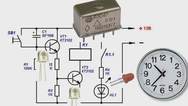
Transistor timing device
The electrical circuit of a time relay on several transistors is the easiest to implement, since it contains only 8 active elements. On its basis, it is possible to assemble devices that control the time for turning off the lighting, for example.To power such a circuit, you need a 9 Volt battery or a 12 Volt car battery.
To make a home-made relay, you need the following set of parts:
- two constant resistors and one variable potentiometer - their values are selected for a specific circuit;
- dual transistor KT937A or a foreign analog;
- load transfer relay;
- constant time-setting capacitor of the required capacity;
- diode under the designation KD105B;
- button to start the relay.
The time delay in a home-made device is organized by charging a constant capacitor to the power level of the transistor key element. Throughout this process, until the voltage reaches 9-12 Volts, the output key remains open, and the bulb connected to it glows in full heat. After a period of time specified by the current value of the variable resistor, the transistor completely closes. As a result, the winding in its collector is de-energized, and the load is disconnected from the power circuit.
Time parameters in seconds or minutes for a relay assembled according to a transistor circuit are selected experimentally - by changing the resistance of an adjustable resistor. For the convenience of subsequently setting the moment of switching on or off, it is recommended to put pointers on the relay housing, which indicate the time settings obtained experimentally.
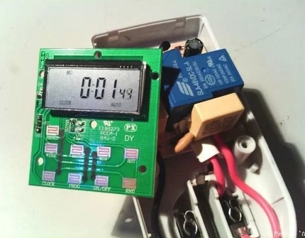
Chip relay
The electronic timer circuit, assembled on the basis of the microcircuit with your own hands, allows you to get rid of such disadvantages of the transistor analogue as the complexity of calculating the delay time. In addition, in the transistor circuit, each time before the next start, it is necessary to discharge the time-setting capacitor. The use of microcircuits on the one hand eliminates these shortcomings, and on the other, somewhat complicates the device. When choosing a microchip suitable for a time relay, proceed from the following considerations:
- if you need a delay in the range from ten minutes to one hour, the TL431 series chip is best;
- if necessary, work with a wider range - with a time delay of 1 second to several hours - it is most convenient to make a timer on the classic NE555 series;
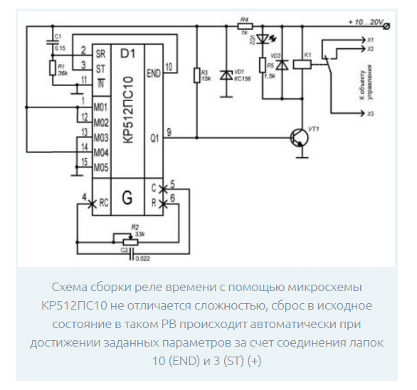
- approximately the same time parameters can be obtained using the KR512PS10 microcircuit.
Due to the presence of a reference voltage source, the response threshold for them is strictly fixed, which allows you to precisely set the required delay time.
The ability to increase the switching voltage allows you to increase the range of time delays up. Due to the presence of a built-in unit for zeroing the charging circuits, there is no need to do a forced reset. The advantages of this version of a home-made time relay include the reduction of false positives, which is explained by more "tough" current modes.
Microcontroller-based relay circuits have become very popular. However, for self-copying, they are not entirely convenient. When using them, there are certain difficulties associated with the soldering of microchips and their programming. Proposed options for timing devices are usually enough for home repetition.
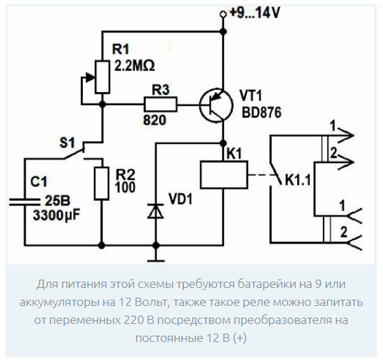
Device for switching equipment 220 Volt
To control the operation of power equipment (electric motors, for example), conventional 12-volt circuits are not suitable. In this case, you need a magnetic starter, switching voltage 220 or 380 volts (depending on the number of phases). To supply a control voltage to its coil, a powerful 220 Volt driver is also required.
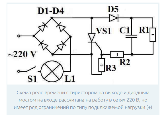
The simplest circuit of such a relay, used only for lighting control, does not need powerful contactors and can be assembled from a limited number of parts. To do this, you need a rectifier bridge of 4 valve diodes and a semiconductor thyristor controlled by the level of AC voltage.When operating as a regulator, the valve passes only the positive part of the 220 volt sine wave. This mode is valid only for circuits loaded on incandescent bulbs, as well as on fan motors or on heating elements. They are not sensitive to the form of the applied voltage, unlike other samples of switched electrical equipment.

For self-assembly of such a timer, the following components and parts will be required:
- constant resistance at 4.3 megohms and 200 ohms plus a variable resistor at 1.5 kOhm;
- four diodes, designed for currents above 1 Ampere and reverse voltage up to 400 Volts (this can be KD202R, for example);
- 0.47 uF timing capacitor;
- VT151 thyristor or a similar element.
The principle of operation of the circuit is similar to the cases already considered earlier and is reduced to charging the time-setting capacitor by the supply voltage.
During the charging cycle, a positive potential is applied to the thyristor control electrode, which maintains it in the open state. As a result, the half-waves of the mains voltage are supplied to the bulb connected to the circuit. At the end of the charging process, the current in the circuit stops, the thyristor closes, and the light goes out. The time delay is adjusted by setting the voltage across the charging capacitor using a variable resistor.
Multifunction devices
Multifunctional time relays produced by the domestic industry are distinguished by an extended range of options, which means that the following features are available:
- Products are able to work according to the schedule specified by the program for a year, month or week.
- They can serve from one to 4 switched channels.
- Equipped with six input control modules.
It makes no sense to copy multifunction devices on your own. They should be considered as samples for an in-depth study of the capabilities of modern time relay models.