The unit called “three-phase voltage stabilizer” is a complex electronic device that allows you to maintain the output power at the right level. The need for these products is caused by the instability of the 380 V power supply, the fluctuations of which sometimes reach dangerous values. When installing stabilizers, it is possible to protect the industrial and household equipment connected to it, which often fails due to voltage exceeding the limit values.
Design features
By their design, a three-phase stabilizer is three single-phase single-phase modules with a common control and monitoring circuit. Two versions of such devices are known:
- In the first case, this is a single design, which includes three independent stabilization circuits.
- The second option is three identical single-phase stabilizers, connected according to the "star" scheme and placed in the form of modules in a single rack.
The first version is used to serve low-power consumers and is relatively cheap. But you have to pay for it with serious problems that are possible during its operation. If one of the 3 schemes fails, the entire structure has to be repaired or completely updated. The second modification (in the form of a rack with independent modules) is characterized by increased functionality, which allows not to interrupt the power supply in case of failure of one of the phase lines. In this case, the voltage is applied to the output directly, bypassing the problem module.
A feature of connecting any modifications is a separate phase supply to each of the converters, while their working zero remains common. In addition, the enclosures of these devices are necessarily connected to the grounding circuit available at the industrial facility.
The control and monitoring circuit of 380 V voltage stabilizers works according to a special algorithm that allows not only to adjust the value of the output voltage, but also to turn off the device in the following emergency cases:
- the voltage value of one of the phases below or above the critical level;
- the temperature of the adjustment elements of the converter modules exceeds a predetermined threshold;
- a strong phase imbalance was detected in the consumption pattern.
A phase imbalance is characteristic of an operating mode with an uneven load, when the phase voltage values are shifted towards the zero of the transformer neutral.
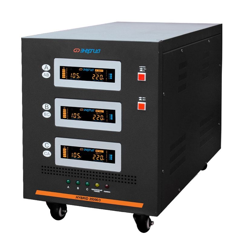
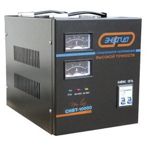
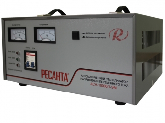
As a protective element, disconnecting the load in an emergency, a 4-pole circuit breaker built into the unit is used. The 3-phase stabilizer is externally designed as a vertically mounted floor structure. In addition to the controls, voltage indicators are displayed on its front panel, made in the form of pointer voltmeters or modern digital indicators.
Principle of work and scope
 The purpose of any stabilizer is to maintain the output voltage at a given level. To understand the principle of its operation, you first need to familiarize yourself with the following features of the internal device:
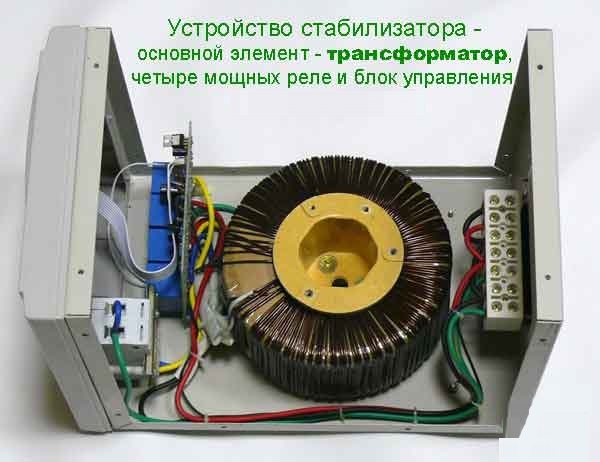
- the basis of most stabilizers is a transformer-transformer with an adjustable number of turns at the output, allowing you to change the voltage on them in one direction or another;
- as long as the input readings correspond to the nominal, normal 220 volts are taken from the output winding;
- if the input voltage has changed up or down, the controller built into the stabilizer processes the difference and provides a control signal to a special motor mechanism;
- the latter moves the voltage stripper motor in the desired direction, adjusting the output voltage until it reaches its nominal value.
Among the models of stabilizing devices produced by the industry, models with smooth and step adjustment are distinguished.
The scope of three-phase stabilizers is quite wide. They are installed in power supply circuits not only in production, but also at home, mainly in private and suburban homes. Stabilizing devices for domestic needs, as a rule, are characterized by a low power indicator, limited to 30-50 kW. More energy-intensive units (up to 100 kW) are often installed in city offices, in suburban villages, as well as in small enterprises.
For a personal summer residence, a device that guarantees obtaining output power up to 50-70 kW is quite enough. Industrial designs of stabilizers with a declared power of more than 100 kW are installed in the shops of factories, in medical institutions, as well as at exhibition venues and in shopping centers. Voltage isolated devices operating in high humidity conditions are in demand in specialized medical facilities, laboratories and research centers.
Types of three-phase stabilizers
The industry has launched the production of a large number of modifications of stabilizers designed for operation in three-phase networks. The list of the main types of such units:
- relay and thyristor devices;
- electromechanical stabilizers;
- ferroresonant and invertor models;
- hybrid appliances.
Each of these positions needs a separate consideration.
Relay and thyristor samples
In relay devices, electromagnetic relays are used to switch the turns of the output coil of the built-in transformer. Systems of this class are distinguished by sufficient speed and are convenient in operation and maintenance. However, due to the mechanical nature of the switching, they are not durable enough (the relay response resource is limited). At the same time, the accuracy of adjusting the output indicators for relay units is insufficient for practical needs.
Thyristor devices do not contain mechanical contacts, since their switching circuit is based on semiconductor devices. Due to this, the indicators of reliability and durability of the stabilizer increase sharply, and the resource is almost unlimited. Thanks to the streamlined production of modern electronic components, the cost of such a device is low.
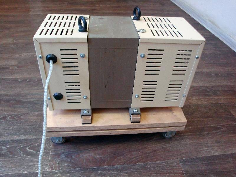
Electromechanical models
In units of this type, the output voltage is adjusted by mechanical movement of the current collector brushes, which is part of the built-in servo drive. This explains the low rate of regulation of the output parameter, not exceeding 15 volts per second. Other disadvantages of these devices include:
- excessive noise;
- strong sparking during work;
- low inertia (the device does not have time to respond to sudden changes in the input voltage).
A positive quality of electromechanical devices is the high accuracy of setting output indicators (voltage and power).
Ferroresonant stabilizers
This type of stabilizing device resembles conventional transformer models, in which the magnetic circuit has a pronounced asymmetry. This differs from standard designs with non-linear magnetic characteristics. A significant drawback of these units is their low power efficiency.In addition, if it is necessary to control large current loads, the linear inductor is obtained of significant size.
To reduce the size and weight of the device, a capacitor is introduced into it, due to which the magnetic circuit acquires resonant properties. Hence the name of this unit is a ferroresonant regulator. Today, this type of stabilizers (as well as its electromechanical counterpart) is used only in special cases. In domestic conditions, they were replaced by modern electronic devices called inverters.
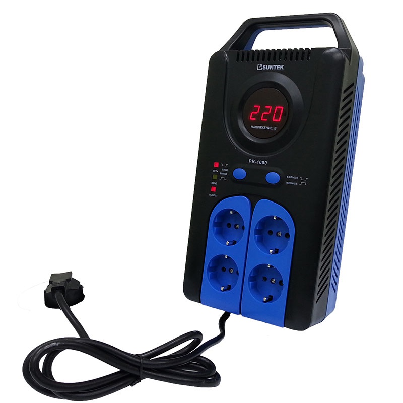
Inverters
Inverter models are built according to a complex electronic circuit that includes several stages of input voltage conversion. Thanks to this, it is possible to obtain an almost perfect regulator, which allows maintaining the output level with accuracy unattainable for other stabilizers. The range of permissible input oscillations is expanded, and the control speed is limited only by the speed of the output key elements (high-frequency transistors). The only drawback of electronic components is their high cost.
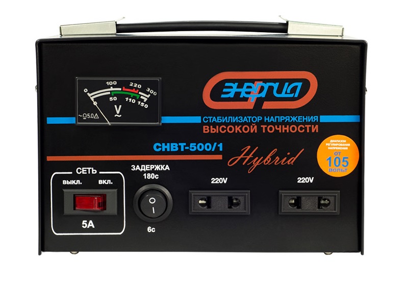
Hybrid devices
This type of stabilizing devices appeared on the market relatively recently (in 2012). The basis of its design is a mechanical regulator, which includes two relay-type converters. In the normal mode, only the electromechanical device works, and additional nodes come into effect when the main module can no longer cope with its functions.
The inability to maintain the optimal level at the output usually manifests itself with too low or too high input voltages, limited by a range from 144 to 256 volts. If this value is less than 144 or higher than 256 Volts, the second stabilization stage, assembled on an electronic relay, starts to work. The maximum adjustment range is from 105 to 280 volts.