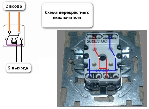
Single-key models of walk-through switches allow you to control a single lighting system from multiple locations. Duplicating devices from standard differ in a large number of contacts. The correct connection diagram of the passage switch will allow the creation of communications with independent control.
Design and differences of cross over switches
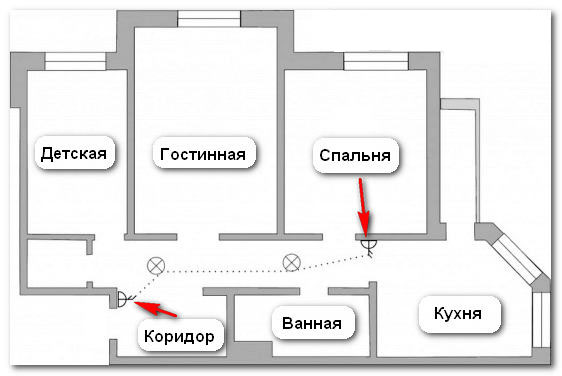
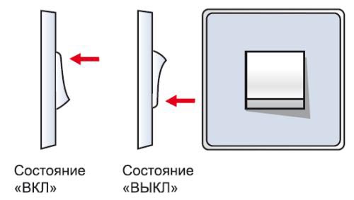
The walk-through switch is used to turn on and off the light from different ends of the room or corridor. Activation of light sources is usually carried out near the entrance to the room, and the shutdown is from another zone.
Duplicate models may look like standard switches. On the front movable side there is a marking in the form of arrows pointing up and down. If the standard switch has one input and one output, then the flip switch has two of them. Such a constructive technique eliminates a current break - it is redirected to the output.
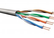
Cross over products have 3 copper contact terminals. Under the case you can see the connection diagram. A simple switch has two-wire switching, a walk-through switch has three-wire switching, for redirecting voltage from contact to contact.
You need to connect paired devices for one light source, with an input to each phase and zero. By changing the position of the button, the user provides a circuit closure - the lamp lights up. Opening the phase cable occurs when turned off - the light goes out.
Keys in one position - the light is on. In different positions - off.
Selection options
Before purchasing a switching device, you must consider:
- type of control - key, sensor or remote control;
- installation method - installation is carried out by waybill (open wiring, on the dowel-self-tapping screws) and built-in (hidden wiring, in the socket boxes on the spacers) method;
- compatibility with light sources - for fluorescent lamps models X and AX are suitable, for incandescent lamps - A;
- degree of protection - it is allowed to install switches with IP03 in bedrooms, in bathrooms with IP04-IP05, on the street - with at least IP55;
- contact clamps - the intermediate device is equipped with screw clamps with pressure plates or screwless fasteners.
Connecting switching products is carried out on a three-wire wire with a cross section of 1.5 mm2.
Where a similar lighting control system is used
The passage switch increases comfort and control capabilities for one lamp or a group of lamps from several places. The technology is used in apartments, public buildings and private houses:
- Stairways. The marching lamp turns on at the bottom, and turns off at the top by a person after climbing the stairs. The circuit allows you to install a time relay, so that the light is turned off independently.
- Long corridors. A convenient option for residents of private homes. If you need to leave the room, use the switch at the beginning so that the light comes on. After overcoming the corridor, it is enough to turn off the light by pressing the keys of another device.
- Passage rooms. The lamp is turned on near the doorway.Entering another room, the user does not return back - the line is de-energized immediately.
- The bedrooms. The light turns on at the door, and turns off next to the bed.
The electrical circuit is relevant for underground passages, in the entrances.
Connecting an intermediate switch
Before connecting the switch, you need to find the circuit on the reverse side. Next you will need:
- Remove the button and the overlay frame from the product.
- After disassembling, find the 3 terminals of the contacts and select the common one according to the diagram on the case.
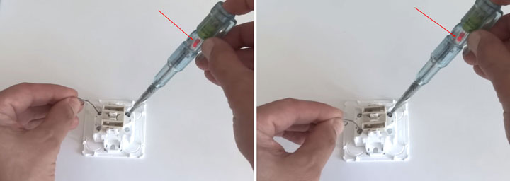
- In the absence of signs or their misunderstanding, you can use a tester or a screwdriver with an indicator.
- Touch the probes of the multimeter to all the contacts and find the one that, when touched, the device will clean, will give a zero value when the keys are turned on or off.
- Use an indicator screwdriver to do a similar test.
- Connect the phase from the power cable to the common terminal.
- Throw the remaining terminals to the two remaining conductors.
The backup device is connected in the same way.
Connection diagram for PV cables in the distribution box
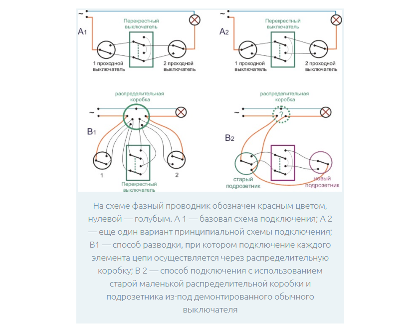
An important step is the assembly of the circuit breaker circuit breaker in the distribution box. 4 wires with 3 wires enter it - a power cable from the light control automat from the switchboard, a cable to the 1st and 2nd switch, a cable to the light source.
In the process, you need to focus on the color of the wire:
- phase - white / gray;
- zero - blue / brown;
- earth is yellow green / black.
The assembly provides the following step-by-step algorithm:
- The connection of the neutral conductor coming from the input cable of the machine and the zero that goes to the lamp with terminals.
- Connection of all veins of the earth in the presence of the grounding conductor. The ground from the input pops into the tap ground with the terminals.
- Grounding connection to the housing of the lighting device.
- Coupling the phase from the input cable with the phase from the outgoing cable and fixing them to a common terminal in the 1st switch.
- Coupling of the common wire of the 2nd switch with the phase of the lighting cable terminal.
- Connection of secondary outgoing conductors of circuit breakers No. 1 and No. 2.
- Supply voltage and design testing.
Stick to color coding so you don’t get confused later.
Features of connecting a single-key switch from two points
The circuit of the switch, controlled from two places, provides for the use of paired devices, a plant for the wires of the lamp and three-wire cable switches in the distribution box. For work, you will need screwdrivers (indicator, flat, cross), a clerical knife, side cutters, a punch, a level and a tape measure.
Connection requirements

The correct installation process includes:
- the functioning of the switches in pairs - they must duplicate each other;
- ditching the wall with hidden installation or using trays / boxes with open wiring;
- factory of cable ends into mounting boxes and connection by contactors;
- the use of 5 cables - 1 for powering the machine, 3 for switches and 1 for lighting;
- the use of a three-core copper wire with a cross section of 2.5 mm2;
- output of zero and earth to the lamp directly;
- the direction of the brown phase wire through the switches to the lighting device;
- tossing circuit breakers in a phase cable break.
The phase through the switch is needed for the safety of repair or replacement of fixtures.
Connection algorithm
The connection diagram of the through switch to 2 points is implemented as follows:
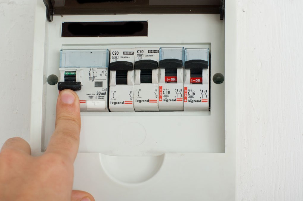
- Disconnect the room through the shield.
- Check for voltage with an indicator screwdriver.
- Removing the ends of the wires of the insulation coating.
- Search for phase cable with an indicator screwdriver.
- Fixing a phase wire with one of the wires (white or red) of the switch using twisting.
- Connection of wires to each other by zero terminals.
- Tucking a separate wire from switch No. 2 onto the lamp.
- Cable twist from the lamp with zero in the distribution box.
The bundle is soldered and wrapped with electrical tape.
Characteristics of touch models of switches
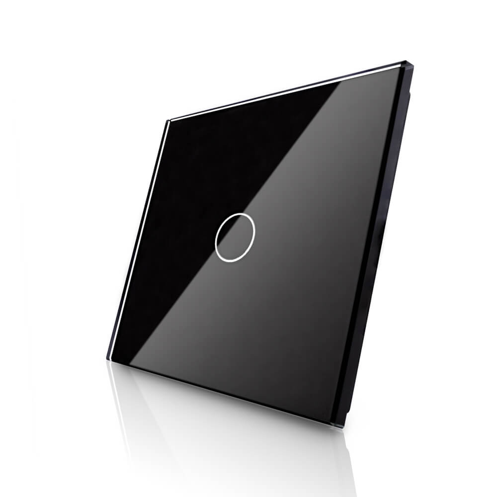
The touch switch of the light sources switches the current through a high-power transistor or thyristor. The signal to open or close the gadget is supplied from a sensor that responds to an external stimulus.
Two types of sensors are used as a sensor - acoustic or motion. There are models with capacitive sensors that respond to touches from 1-3 cm. The devices are controlled remotely, which increases their functionality.
Externally, the touch-sensitive single-key switch looks like a smooth glass panel. Light indication is noticeable at the time of connection. Red indicates on, blue indicates off. Incandescent or discharge lamps can be connected to the devices. The group of touch switch and LED lamp malfunctions, but fixes the problem through a special adapter.
Basic connection errors

In the process of assembling a synchronous design, novice masters make several mistakes:
- Use of more than 2 transitional switches. The costs of cable and distribution boxes are increasing.
- Wrong common terminal selection. A single contact item can be anywhere. To find it, you need to make the dial with a multimeter or indicator screwdriver.
- Confused wires. The problem occurs when installing devices from different manufacturers.
- Incorrect connection of cross models. Two cables of device No. 1 are placed on the upper contacts, and device No. 2 on the lower contacts. It is necessary to make an exception and put them cross-on-cross.
By the backlight, the cross type of the switch cannot be identified.
Cons of the through switch
Despite the quality of light control and increasing the comfort of living in an apartment or house, duplicate switches have disadvantages:
- There is no marking of turning off and on of keys, as with standard models. For this reason, it is not possible to determine when the lamp burned out. To replace it, the light switch is de-energized through the shield.
- A large number of twists in the distribution box. The number of connections depends on the number of light points. You can reduce twisting by connecting the cable directly, but this will increase its footage. For ceiling lights, you will need to draw the wire up, lower it down, connect it to the switch and bring it back up. The problem will be solved by a pulse relay through which the cable will pass.
- Lamps from different points do not turn on and off at the same time.
Minor disadvantages practically do not affect the quality of the devices. If the switch circuit is implemented by yourself, at first the user may get confused.
The convenience of walk-through switches saves time returning from one end of the room to the other to turn off the lights. All models look neat, stylish, with the right connection they will last for several years.