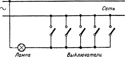
In long hallways or corridors, a walk-through switch is often installed - a 3-point connection diagram ensures the equivalence of sections of the electrical circuit. The user can press any key from which the lighting will turn on or off.
Design and features of passage switches
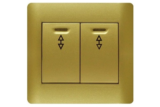
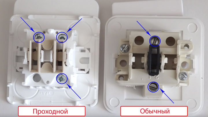
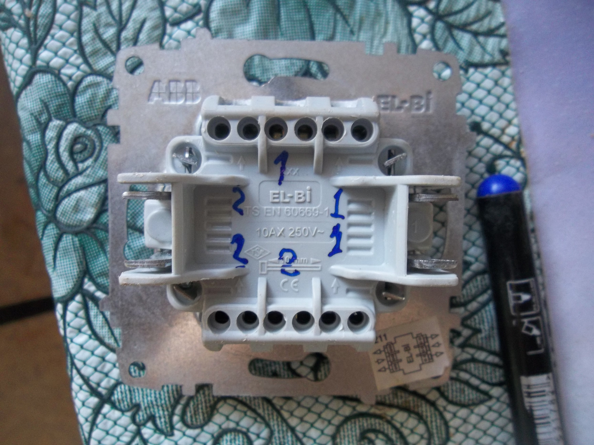
The external pass-through device does not differ from the standard. The difference can only be noticed when inspecting the product from below - manufacturers put triangles on the case, directed horizontally down.
The second variant of the difference is 3 terminals with copper contacts. One is located above and two below. Also, the feed-through device is switched through a three-core cable VVG-ng or NYM with a cross section of 1.5 mm2.
Depending on the number of buttons, there are two-key, one-key and three-key modifications.
In comparison with the classic bipolar models, you need to connect the sink using the following principle:
- serial connection of switches;
- the phase does not open, but switches to the second line;
- there are more output contacts than input contacts.
The paired poles of the switches are located opposite each other.
The nuances of choice
Before buying a passage switch, you must consider:
- Mounting method - depends on the type of wiring. Overheads are installed on the surface using dowels, self-tapping screws. Built-in - in the rosette on the strut legs.
- Degree of protection - models with IP03 are suitable for a bedroom or a corridor, for a bathroom - with IP04-IP05, for a street - with IP55.
- Type of contact clamps. Screw with pressure plates are reliable. Screwless springs are easier to install.
- Terminal marking - N (zero), L (phase) and ground (ground) are used. The letters I and O mark the position of the buttons when turning on and off.
By type of control, the walkers are keyboard, touch, with remote control.
Circuit application
Walk-through models are intended for the convenience of supplying or removing voltage of lighting devices from different ends of the room. Most often, such a scheme is used:
- In a long corridor with exits from different rooms. They put one switch at the output, in the middle - the second, at the end - the third.
- In the yards of suburban and private houses, cottages. Switching devices are mounted at the exit from the house and outbuildings.
- In multi-storey three-story buildings. An appliance is placed on the ground floor to turn it on. You can turn off the lighting on the second and third floors.
- In the children's room with multiple beds. The solution provides for one device at the entrance and two next to the berths.
- Stairways and cottage grounds in the country. One device is mounted at the beginning of the stairs, turning off is carried out from the second floor or near the attic.
By means of a passage switch, energy is saved.
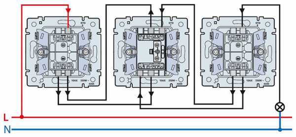
Connection of the through switch from 3 places
 To connect a circuit with three devices for each point, you will need your own switchboard that implements lighting control. The circuit-breaker circuit breaker from three places provides for the installation of a straight-through switch with 4 contacts in the center. The extreme nodes will work at two points, depending on the position of the aisle. The light will not light up at different positions of the two extreme switches.
The loop-through device will redirect the phase from the contact at the top of the input switch to the lower output contact:
- The buttons are directed down - lighting is not active. We press switch No. 1 - the phase is sent along the circuit in one line, the light comes on.
- Dimming of light from switch No. 2. The button is pushed up. The line opens, there is no phase at the input.
- The switch button No. 3 is at the top. The circuit closes, the lighting lights up. To disable it, you will need to change the position of the switch.
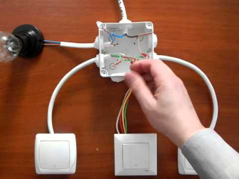
The peculiarity of this scheme is that all actions are performed only with the end of the phase, which prevents closure. Installation of the system is carried out from a distribution box or by direct connection of switching cables.
Direct connection will save wire.
What you need to accomplish the task
With your own electrical work, it is worth purchasing:
- junction box;
- Light source;
- 2 passage switches;
- 1 cross switch;
- 3 sockets;
- cable with 2, 3 and 4 cores;
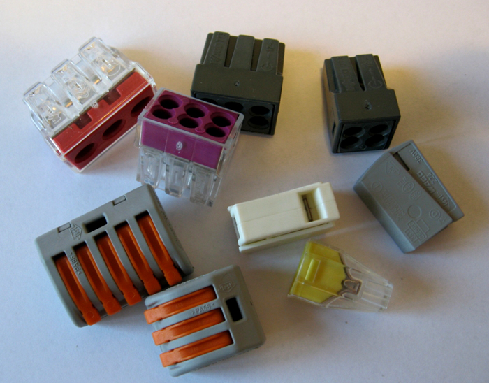
- self-clamping terminal blocks;
- marker;
- colored electrical tape or heat shrink.
To accomplish the task, side cutters, screwdrivers, a knife for stripping insulation from cores, a multimeter, a device for gating will be necessary.
Cross disconnect principle
For the connection scheme of lighting from 3 places, a cross switch is often used. It looks like a single-key device externally, but inside there are 4 terminals. A cross device is called because it switches two power lines.
The disconnector provides a one-time disconnection of switches No. 1 and No. 2. Connection of nodes is also carried out synchronously. The lamp lights up and turns off when moving contacts.
When organizing a larger number of points, the process of connecting parts inside the distribution box is complicated.
Installation work
Installation of the lighting system is carried out according to this algorithm:
- Search the common terminal point on the guide.
- Connection to the first switch next to the phase distribution box.
- Fasten phase to common terminals with orange or red cable.
- Connection on the output internal terminals of the feed-through device of the 2 remaining conductors.
- Throwing on the second switch of a wire and fixture according to a color marker.
- Connecting an orange / red conductor from switch No. 2 inside the box to the bulb phase.
- Connection inside the distribution box according to the color designation of 2 free wires to the circuit breaker No. 1 core.
At the end, neutral and ground are connected inside the box to similar wires connected to the lighting device.
Two-key
To control the operation of light sources from two points, a two-key conductor with 6 contacts is used. Installation of the passage switch occurs as follows:
- Discover shared contacts.
- Phase wire feed to the input of switches No. 1 and No. 2.
- Connecting the remaining inputs with a switch to the ends of lamps No. 1 and No. 2.
- Connect the free ends of the lamps to the neutral cable.
- Throwing 2 outputs of switch No. 1 to the outputs of switch No. 2.
- Similar fastening of the remaining exits.
When using two double-keys, the length of the wires increases.
Three-key
 The three-key device is similar to the two-key type of connection. The difference is that you need to add a fourth wire. Through one cable, the phase is fed to the circuit breaker, in three it goes to the load. Installation is as follows:
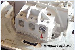
- Find the terminals for connecting the phase conductors on the sides of the contact block.
- Connect the No. 1 phase cable on the side of one terminal.
- Connect the remaining three phase wires to three terminals.
- Start phase No. 1 in the distribution box and connect to the cable wire leading to the switch.
- At the input, the phase is brought to the lower input contact.
- From the three output contacts of the switch at the top, three phase cables are diverted to the distribution box and connected to the wires leading to the ceiling.
- On the ceiling, the phase wires snap onto the terminals of the fixtures.
The neutral must be brought into the distribution box and connected to the wire directed to the ceiling. There zero must be connected to the blue point of the conclusions of the fixtures to form a common conclusion.
Connection errors
With independent switching, novice electricians and home masters often make a number of mistakes:
- Incorrect phase to zero connection. The passage switch breaks only the phase. The wrong circuit without affecting the wiring of the passage switch controlled from 3 places is corrected by reconnecting the wires in the distribution box.
- Violation of the sequence of phase and zero. The problem is indicated by inoperative switches in one position.
- The two-key is installed correctly, but does not work. By mistake, a standard switch was purchased, which, if there is a receipt, will be replaced in the store.
- Connecting the line to the wire with the wrong cross section. The fourth core of the cable has a diameter 1/3 less than the rest. It is not connected to the phase, but only to the ground loop.
- Parallel connection. When organizing intermediate control, only a serial circuit is used with the passage of the same phase.
If the connection rules are violated, there are risks of electric shocks when replacing the light bulb; a circuit breaker may short circuit. The wiring also burns out and the conductor breaks.
Disadvantages of passage switches
The organization of a power line with a passage switch has several disadvantages:
- time and effort spent on wall breaking with hidden wiring;
- the need to connect the remote control via a regular key for models with motion sensors;
- unprofitability for an apartment because of the cable gates and the installation of a din rail;
- difficulties with the definition of terminals;
- lack of clarity on and off.
Experts note that the devices are more suitable for suburban cottages, cottages, the private sector than for an apartment.
The passage switch is convenient to use in rooms with several groups of lighting fixtures. The device provides the comfort of light control, the safety of moving people. Currently, the scheme of the passage light switch, controlled from three places, is not tied to the layout of a residential object.