Water supply and sewerage are part of the arrangement of buildings and structures where people live, rest and work. Installation of water supply and sewage networks is carried out according to individual projects.
How is the design of water supply and sanitation
The design of water supply and sewage systems is carried out in stages. Initial information about the object is collected: general plan with communications, geological characteristics, technical conditions. On the basis of the received data form the technical task and make up the project.
Project development solves the following tasks:
- Calculation of water consumption, required water pressure, volume of effluents.
- Drawing up a plan for water supply and sanitation.
- The choice of materials and equipment.
First, the source of drinking water is determined: a central water supply, a well or a well. If city networks are not connected, choose the appropriate method for producing hot water: a heat exchanger, an electric water heater, or a gas boiler.
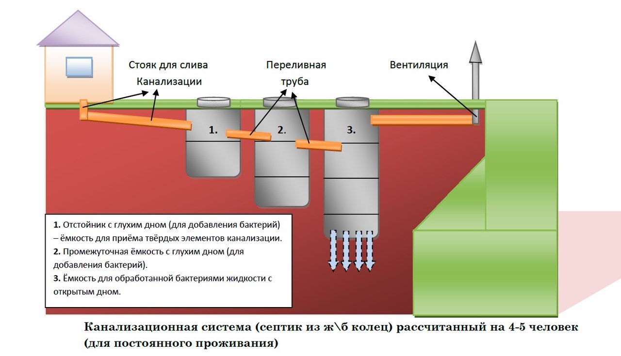
Assign the installation location of the septic tank if there is no connection to the general sewage system. The septic tank is designed at a distance of 30 m from the well, and the main sewer riser is located at the wall closest to it. Draw an external plan of water supply and sewerage to the point of entry into the foundation of the building.
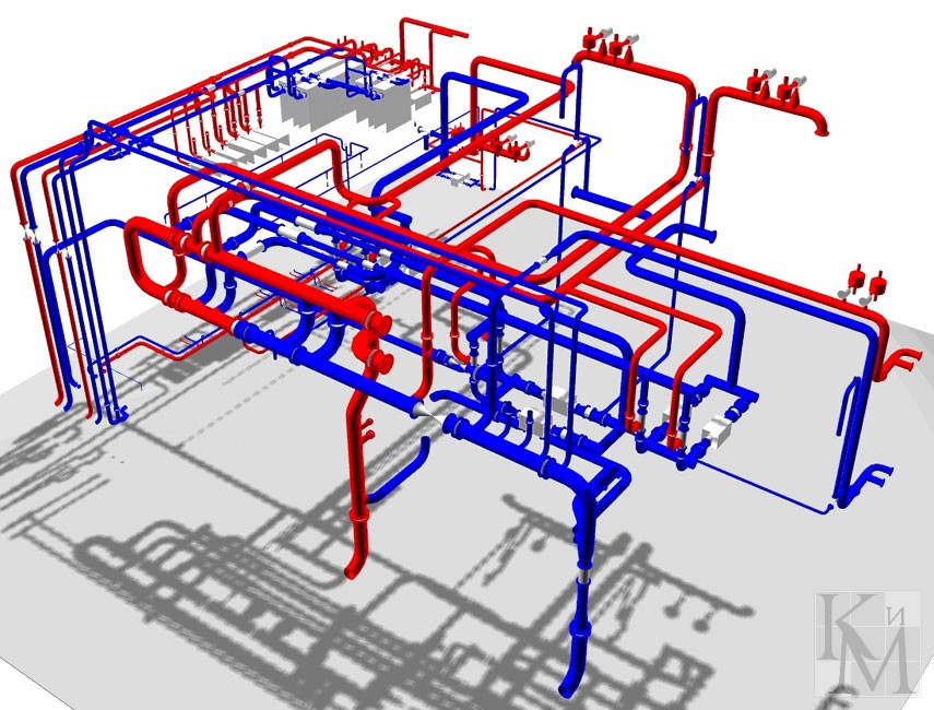
Draw up a drawing of the internal wiring of water and drain pipes with an indication of the lengths, diameters, points of installation of plumbing equipment. Network wiring projects for multi-story buildings are carried out on one or more vertical risers.
The number of plumbing fixtures and users determines the required pressure, water consumption, drain volume. They calculate these characteristics, set the diameters of the pipelines, and the parameters of the pumping station.
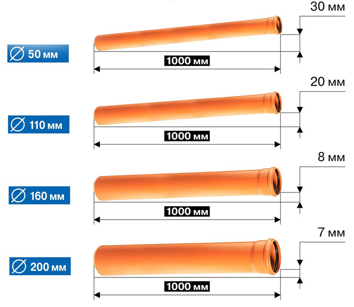
The diameter of the main external sewer determines the slope:
- Ø 110 mm - 0.02
- Ø 160 mm - 0.008
It is not allowed to decrease and increase the drainage slope angle, since the transporting capacity of the liquid is maximum when the calculated value is observed.
The choice of materials and equipment is the final stage in the design of water supply and sewage. Materials are selected, taking into account operating conditions, network load, price limit.
Architects lay in the project the possibility of modernization, expansion, repair of the complex in the future. This allows you to eliminate damage during installation and install new equipment.
The finished water supply and sewage project contains floor drawings, an explanatory note with calculations, a specification of materials.
What governs SNiP in the design of engineering communications
They design water supply and sanitation based on SNiP 2.04.01-85. The normative document prescribes a set of rules, according to which they develop water supply and sewage plans for residential buildings, public buildings, and industrial enterprises. Local treatment facilities are designed in accordance with SNiP 2.04.03-85, taking into account the construction standards of regional departments.
Sewer pipelines are laid in a straight line with a given slope, which is not allowed to be changed. Attaching devices and changing the direction of the pipes is done by connecting elements that have a smooth, streamlined angle of rotation.
There are two options for arranging the internal sewage system:
- Open fastening of pipes to walls, supports, ceilings.
- Concealed installation in ducts, shafts, floor structures, floors, wall cuts, followed by termination.
The internal pipelines protect against mechanical damage, and the external ones are insulated and buried under the ground to the calculated depth. Sewer risers lead to the roof of the building or to a prefabricated exhaust shaft for ventilation.
Cleaners design in places where drains turn, at dead ends, on risers. In multi-storey buildings, riser revisions are installed on the upper and lower floors, as well as on floors above the indentation. In houses with a height of 5 floors, revisions are made through 3 floors.
Document SNiP 2.04.01-85 regulates compliance with additional rules when designing water supply and sewage systems in buildings that are built in special climatic and natural regions. These include permafrost and subsidence soils, as well as seismically dangerous and undermined territories.
Compliance with building codes during the design will protect the system from possible breakdowns and incorrect operation in the future.
Carrying out the necessary calculations
The design of water supply and sanitation systems includes calculations of water pressure, water consumption, wastewater volume, as well as estimates of material costs. Calculations are appropriate for multi-story buildings. In small one-story buildings, standard solutions are used.
Calculation of water supply is carried out to determine the pressure of water on plumbing fixtures. If the pressure is insufficient, make changes to the water supply plan: increase the capacity of the pump, change the diameter and length of the pipes.
The loss of water pressure as a result of selection by consumers and ascent to the upper floors is calculated by the formula:

Where:
- H - pressure loss (m),
- λ is the coefficient of friction indicated in the pipe marking,
- L is the length of the line (m),
- D is the diameter of the pipeline (m),
- g - constant: 9.81 m / s2,
- V is the velocity of the water (m / s).
Formula for determining the flow rate of water:

Where:
- D is the inner diameter of the pipe,
- π - constant: 3.14,
- Q - water flow rate (m3 / s), taken in accordance with Appendix 2 of SNiP 2.04.01-85.
Water consumption depends on the number of residents and the type of equipment installed. The values for different devices and their dependence on the number of water consumers are indicated in tables SNiP 2.04.01-85.
Hydraulic calculation of a drainage system with a diameter of up to 500 mm is made according to the nomogram of Appendix 9 of SNiP 2.04.01-85, and for large diameters SNiP 2.04.03-85 is guided.
Complex technical calculations should be entrusted to design engineers. Specialists will not make mistakes in the preparation of the project, which guarantees reliable operation of communications.
Material selection
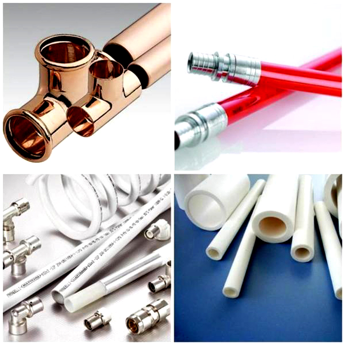
The water supply and sewage project includes the selection of pipelines with the required parameters. The industry produces a wide range of pipes for domestic and drinking water and wastewater.
Materials for the manufacture of pipelines:
- metal plastic
- cast iron,
- steel,
- copper,
- polyethylene,
- polypropylene,
- polyvinyl chloride
- fiberglass
- asbestos,
- reinforced concrete.
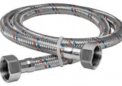
The most widely used products are from polymers, metal, stainless steel. Domestic water pipes are made of PPRC polypropylene, metal-plastic, cross-linked PEX polyethylene, corrugated stainless steel. Internal drain pipes are made of PP polypropylene, gray PVC and high density polyethylene HDPE.
For external water supply systems, products from PE polyethylene and polyethylene with a protective layer PE-RC are used. External drainage systems are made of orange polyvinyl chloride, corrugated polyethylene and corrugated two-layer PP polypropylene.
The designer accepts the type of pipe, based on the technical conditions of the project, the advantages and disadvantages of the material, and also takes into account the wishes of the customer.
Stages and features of arranging water supply and sewage networks
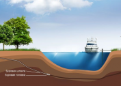
 According to the finished project for water supply and sewage, the arrangement of networks and equipment is carried out. The creation of an autonomous network begins with drilling a well or digging a well.
Install a water source: pump, autonomous water supply station. Mount water purification filters. Build a septic tank or bio-treatment station. An alternative option for a summer residence is a storage tank or cesspool.
They dig trenches for external water supply and sewage lines. They fill the bottom of the trenches with sand, put insulation on the pipelines, and lay with a given slope. Drain into the hole of the non-settled septic tank set freely until precipitation. Lead the lines to the building, connect to the internal network.
Water pipes are subject to freezing in the winter, so they are laid below the depth of freezing of the soil. The best option is a well and a pump are inside the house extension, then there is no need for external water pipes.
Internal horizontal pipelines of the first level lead from the entry point with a constant slope to it. On the next floors, a bias is made to the point where the line joins the riser.
Instrument wiring is done using fittings. Turns of lines are performed by corner fittings. Risers are installed vertically with a ventilation outlet on the roof.
The final stage is the verification and final debugging of the networks. They feed water, examine lines with devices for leaks. Troubleshoot if necessary. If there are no shortcomings, then the internal pipelines are closed or closed, and the external ones are covered with soil.
Hidden pipelines are closed after a special check. They are supplied with water under excessive pressure, which can withstand several hours.
Designing water supply and sewage networks is inextricably linked with the construction of facilities where people are present. The reliability of communications depends on the accuracy of the design.