Hydraulic calculation of a water supply system - a set of calculations performed at the design stage of a building (multi-storey building, cottage). The role of this type of work is very important - an improperly designed water supply system will not function normally. This can be expressed in a weak water pressure on the upper floors of high-rise buildings and in frequent breakouts of basement communications due to high input pressure.
The objectives of the hydraulic calculation of water supply networks
 The main objectives of the hydraulic calculation of the building's water supply system are:
- calculation of the maximum water flow in individual sections of the water supply system;
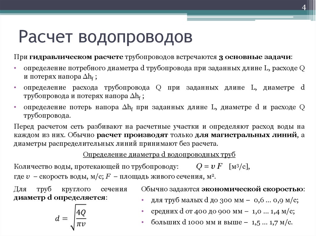
- determination of the speed of movement of water in pipes;
- calculation of the inner diameter of the pipes for the installation of various sections of the water supply network;
- calculation of the pressure loss of water when it is supplied from the main pipeline to a certain height;
- determination of the power of pumping equipment and the appropriateness of its use, taking into account the calculations made.
Calculations are performed based on data and methods of SNiP 2.04.01-85 “Internal water supply and sewerage of buildings”.
Options for hydraulic calculation of water supply networks
Depending on the objectives, two types of hydraulic calculation of water supply networks are distinguished - design and calibration (commissioning).
Design
This type of hydraulic calculation is performed when designing the building's water supply system. With its help determine the type of pipelines for different sections of the network, the flow rate in them.
In addition to calculations, this type of calculation includes a schematic arrangement of the elements of the internal water supply - input unit, basement communications, risers, draw-off units.
Verification
The main objectives of this type of hydraulic calculation is to determine the distribution of flows in the water supply system, to calculate the pressure of the sources with previously calculated internal pipe diameters and water withdrawals at nodal points.
The results of verification calculation are:
- water consumption and pressure losses in all parts of the water supply system;
- the volume of water supply from the source (main water supply system, water tower or counter reservoir);
- piezometric heads at various points of the drawoff.
All the values obtained as a result of this calculation are used to design the location of the water points - plumbing fixtures - inside the designed building.
Accurate and fairly quick adjustment calculation of water supply networks of various configurations (from a simple dead-end water supply system to a more complex ring system) can be performed using the programs: HydroModel, Smart Water, WaterSupply, and Hydraulic Pipeline Calculation.
Hydraulic Calculation Procedure
 The hydraulic calculation of the water supply system includes the following steps:
- Determination of the number of drawoff points - for this, the number of wash basins, bathtubs, and toilet bowls in the building is determined by the standard building plan.
- Drawing up a schematic image (axonometric diagram) of the internal water supply network — manually or using special software, an arrangement is made of the location of the risers and the plumbing fixtures connected to them. Moreover, for the convenience of further work, each hot and cold water supply pipeline is marked with different colors (red and blue, respectively).
- Dividing the water supply network into separate calculated horizontal and vertical sections, consisting of pipelines and water distribution units. The boundaries of each site is shutoff valves and plumbing fixtures.
- Calculation of the probability of the simultaneous inclusion of all the water-collecting units of the calculated section (P) - the calculation of the value of this value is performed according to the following formula:
P = Q max water × U / Q approx. × N × 3600;
WhereQ max water –Water consumption in hours with maximum water consumption, l / h per 1 inhabitant;
U - the number of residents who are provided with water by communications and water draw-off nodes of the settlement site, people;
Qapp. - the standard flow rate through the pumping unit averages 0.18 l / s;
N - the number of water analysis units (plumbing fixtures) included in the design section, pcs;
3600 - coefficient used to convert liters per hour to liters per second.
- Determination of the maximum second flow rate of water by the pipeline and the water intake nodes of the calculated area according to the formula:
Q max. Water input = 5 × Q in. Surf × a; l / s
Where Q century surf - the total standard flow rate through the sites of the site;
a - the size is dimensionless. Its value is found by special tables in SNiP 2.04.01-85.
- Selection of the optimal internal diameter of the pipeline - is selected taking into account recommendations for use and economic feasibility of use in these conditions.
- Calculation of water speed - calculated by special methodological aids, based on the inner diameter of the selected pipeline.
- Head loss calculation (Hl) according to the formula:
Hl = L × i × (1 + Kl); m.water column,
Where L - the length of the calculated section, m;
i - specific pressure loss during friction of water against the inner walls of the pipeline, this value is measured in millimeters of water column / meter of the pipeline;
Kl - correction factor, when designing residential apartment buildings and cottages, its value is 0.3.
- For buildings with 2 or more floors, the hydraulic calculation of the required pressure (Ntr) of the water inlet at the point of its connection to the external main pipeline is carried out according to the following formula:
Htr = 10 + (n-1) × 4,
Where n - number of floors;
4 -the pressure necessary to raise water for each floor located above the first, m.
- Actual required head at the point of entry (Nf) are found by summing the calculated input head (Ntr) with pressure losses in the design sections (Hl):
Нф = Htr + Нl calculation part 1 + Нl calculation part 2 + Нl calculation part 3 + Нl calculation part 4 + Нl calculation part n
The results of this calculation are recorded in the pivot table.
A pressure of 10 meters of water is equal to the pressure in the water main equal to 1 atmosphere (1 Bar).
Calculation example of cold water supply
Initial data:
The building is a 2-storey house with a basement, one vertical riser height from the basement to the top -6 m, 5 draw-off points (kitchen sink, bath and washbasin faucet, toilet bowl, on the first floor; toilet bowl and shower faucet - on the second floor). A family of 6 lives in the house.
Calculation Sequence:
- The designed internal water supply system is divided into 2 settlement sections - the first and second floors. The length of the communications of the first section is 5 m, the vertical riser and horizontal communications of the second section is 5.5 m.
- Using the tabular data of SNiP, the probability of the simultaneous inclusion of all the water-collecting units for the first and second design sections is calculated:
P1 = 15.6 × 6 / (0.1 + 0.18 + 1.4) × 3600 = 0.015;
P2 = 15.6 × 6 / (1.4 + 0.18) × 3600 = 0.016.
- Maximum consumption of these sections, taking into account the corresponding coefficient values found in the tables a will be equal to:
Q max. Water consumption1 = 5 × Q century. Surf × a = 5 × 0.18 × 0.265 = 0.24 l / s;
Qmax.spray water2 = 5 × Q.prib × a = 5 × 0.18 × 0.241 = 0.22 l / s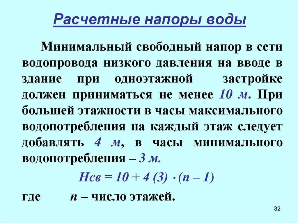
- Given the obtained values of water flow, the internal water supply is designed from a simple polypropylene pipe with a diameter of 25 mm (horizontal bends from the riser) and 32 mm (vertical riser).
- Based on the length values of the first and second settlement section, the coefficient value i and Kl (for such conditions they are equal to 0.083 and 0.3, respectively) the pressure loss in the first and second calculation section will be equal to:
Нl site 1 = L1 × i × (1 + Kl) = 5 × 0.083 × 1.3 = 0.54 m. Water. pillar;
Нl part 2 = L1 × i × (1 + Kl) = 5.5 × 0.083 × 1.3 = 0.59 m. Water. pillar.
The total pressure loss in the two calculated sections will be equal to 1.14 water column or 0.114 atmosphere.
- The required pressure at the entry point for such a building will be equal to:
Htr = 10 + (2-1) × 4 = 14 meters of water or 1.4 atmospheres
- The actual required pressure at the entry point for this cottage will be equal to:
Нф = Нтр + Нl calculation area 1 + Нl calculation area 2 = 14 + 1,14 = 15,14 meters of water column or 1,5 atmosphere
Thanks to the calculation, the owner of the house at the design stage, taking into account the pressure of the main water supply pipeline of his settlement, can plan a certain scheme of the internal water supply network.