Creating an optimally functioning duct system is impossible without aerodynamic calculations. These data allow you to choose the diameter of the cross section, the power of the pipes and fans, the number of branches, materials. Modern requirements are regulated by the set of rules of the joint venture 60.13330.2012, as well as in GOST and SanPiN. The calculation is performed according to a strictly defined algorithm using well-known formulas. To accurately determine all the criteria, you can use the help of specialists or calculate the parameters yourself.
Types of ducts
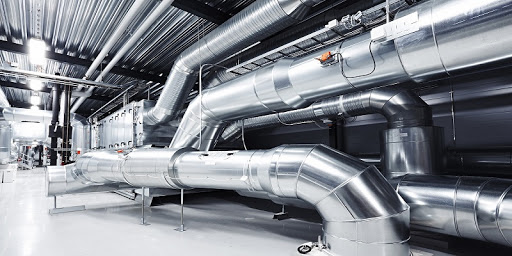
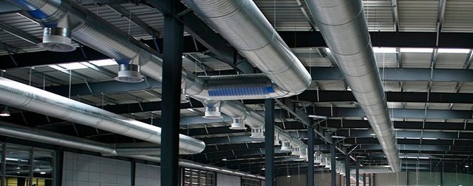
Modern air ducts can be classified according to several parameters: installation method, manufacturing material, sectional shape.
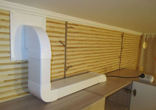
On installation, external and built-in channels are distinguished. The first are installed on top of the walls and visible to the eye. Internal mount in the walls and construction of the house.
The material of the pipes may be different. These are various metals (copper, steel, aluminum) and plastic. Metal products are distinguished by their strength and reliability, but their installation is more complicated. Installing plastic devices is easier, but they are not used at high temperatures.
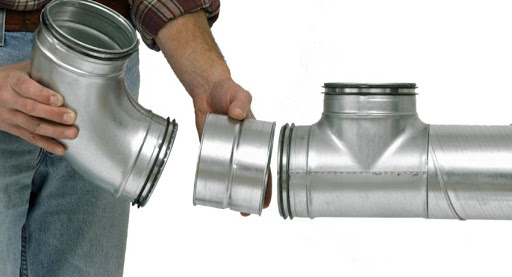
The cross section can be rectangular and round. Rectangular tubes are versatile, but turbulence can be created at the corners. Round models do not have such a drawback.
Step-by-step aerodynamic design of air ducts
The work includes several stages, at each of which a local problem is solved. Based on the data obtained, various parameters of the ducts are calculated.
The main objectives of the ventilation system equipment:
- Fresh air intake from the street and its transfer into the premises. An additional function is the heating of air masses in winter and cooling in summer.
- Purification of air from dirt, dust and fluff.
- Decrease in sound pressure.
- Uniform distribution of fresh air throughout the apartment.
- Removal of exhaust air and its removal to the street.
The ventilation system is characterized by the following parameters:
- Working body. In this case, it is air. It is characterized by density, dynamic viscosity, kinetic viscosity. These values depend on the temperature of the working fluid.
- The speed of movement of the working fluid.
- Local aerodynamic resistance of air ducts.
- Pressure loss.
The algorithm for aerodynamic calculations:
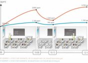
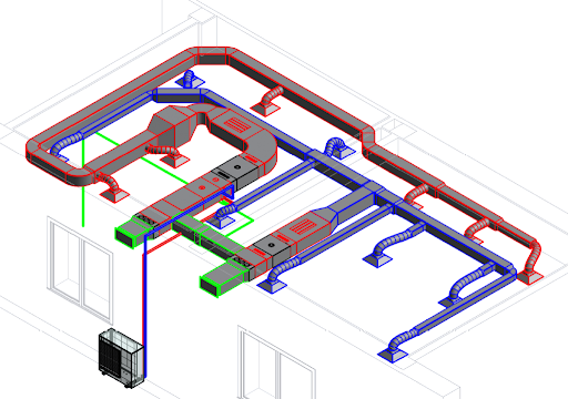
- Development of an axonometric diagram of the distribution of air masses in channels. On its basis, the best calculation method is selected taking into account the peculiarities of ventilation.
- Carrying out aerodynamic calculations on the main and additional highways.
- Selection of the geometric shape and cross-section of the pipes. Determination of technical characteristics of fans and heaters. Determining the possibility of installing fire extinguishing sensors, automatic control of ventilation power.
These are the main stages of the calculations.
All the data obtained can be collected in a table, and then select the materials to create the channel.
Settlement
The main goal of aerodynamic calculation is to determine the air circulation resistance in each part of the system.
There is a direct and inverse problem of aerodynamic calculation. Direct deals with the decision of designing ventilation systems and consists in determining the cross-sectional area of each section of the system. The inverse problem is solved by determining the air flow in a given area.
For the calculation, it is necessary to determine the rate of air exchange. This is a quantitative characteristic of the system, which shows how many times in an hour the air in the room was updated. The indicator depends on the characteristics of the room, its purpose.
Creating a system diagram in axonometric projection is done on a scale of M 1: 100. It is necessary to apply air ducts, filters, noise mufflers, valves and other ventilation components to the circuit. According to the data obtained, the length of the branch, the flow rate in each section is determined, and the duct resistance is calculated.
After that, the optimal pipe laying line is selected. This is the longest chain of successive sections.
If the circuit has several highways, the main one is the one in which there is more flow.
Basic formulas in the calculation
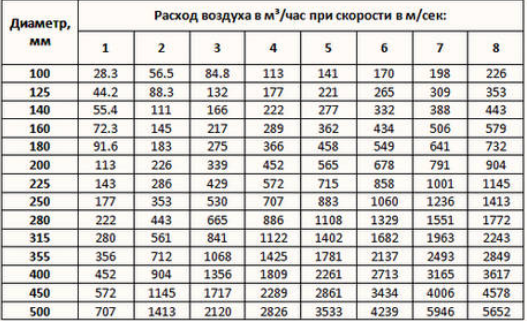
The cross section of the duct can be round and square. It is calculated by the formula F = q / vwhere under Q air flow is indicated, and v - Recommended air speed (reference value).
The diameter of the section is determined from the area Dif the pipes are round in shape or height and width AND and AT for rectangular. Values are rounded to the nearest larger standard and get ANDst and ATst.
For rectangular ducts, the equivalent diameter is calculated by the formula DL = (2Ast*ATst) / (ANDst + Bst).
The value of the Reynolds similarity criterion is calculated as Re = 64100 * Dst * vfactic. From this indicator depends on the coefficient of friction, which is determined by the formulaλtr = 0.3164 ⁄ Re-0.25 at Re≤60000, λtr = 0.1266 ⁄ Re-0.167 at Re> 60,000.
Coefficient of local resistanceλm is selected from the directory and then substituted into the formula for pressure loss in the design section P = ((λtr* L) / Dst + λm) * 0.6 * v2 fact. L - the length of the calculated section.
When summing all the losses, the total losses of the main and the ventilation system are obtained. Based on these values, a fan with a margin of 10% is selected. From its characteristics consider efficiency nand then power N = (Qvent* Pvent) / (3600 * 1000 * n). Here Qvent, Pvent - air flow and pressure generated by the fan.
The calculation of the pressure loss in the duct can be performed by the formulaDP = x * r * v2/2where r - air density v - speed of movement, x - coefficient of local resistance.
Possible mistakes
The calculation of the ventilation system is lengthy and consists of several stages, at each of which mistakes can be made. The most common problems:
- Rounding down the cross section of gas pipelines. Then there may be excess noise or the inability to pass the required amount of air flow per unit time.
- Incorrect calculation of the length of the duct section. It leads to incorrect equipment selection and an error in calculating the speed of movement.
The whole project requires careful and competent calculation of aerodynamics. If it is impossible to independently calculate the system, you can use the online calculator or seek help from specialists.