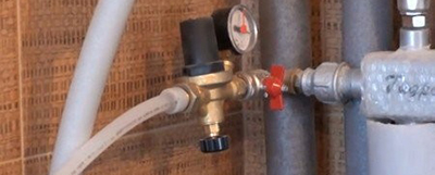
An automatic heating system make-up valve is used to add fluid to the heating circuit. The device prevents breakdowns due to excess pressure in the circuit and water hammer. The design of the module includes a non-return valve, a pressure regulator, a shut-off valve. Elements are complemented by a valve to control closure.
Purpose of the make-up valve
The area of use of the module is autonomous heating lines of houses and structures. Regular coordination of the volume of water in the system is carried out so that when the pressure increases, leaks and deformations of the pipelines do not occur. The reduced pressure of the heat carrier threatens with cooling radiators and sections of the warm floor.
Reasons for reducing water pressure:
- automatic inclusion of air vents;
- natural evaporation;
- the use of Mayevsky cranes;
- filter replacement and other preventive measures;
- actuation of safety valves;
- the property of polymer pipes to expand under the influence of heat.
The filing module facilitates filling the system with energy. On the manometer, the working zone of the normal pressure indicator is always highlighted, and deviation leads to blocking of the heating unit.
Valve characteristics
The auto-make-up unit maintains a uniform fluid volume and pressure in accordance with the instructions of the boiler manufacturers.
Valve Specifications:
- the greatest pressure in front of the device is 10 bar;
- pressure behind the valve (adjustable) - 05 - 3 bar;
- flow rate - 1.85 m3 per hour;
- sensitivity - 0.2 bar;
- maximum system heating - up to + 40 ° С.
The module is connected using a hose with a diameter of 1 / 2´´ at the inlet and outlet. The pressure gauge socket has a 1 / 4´´ thread. The antifreeze pressure in the system is adjusted using a manometer.
Management methods
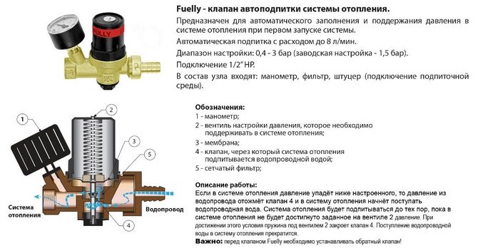
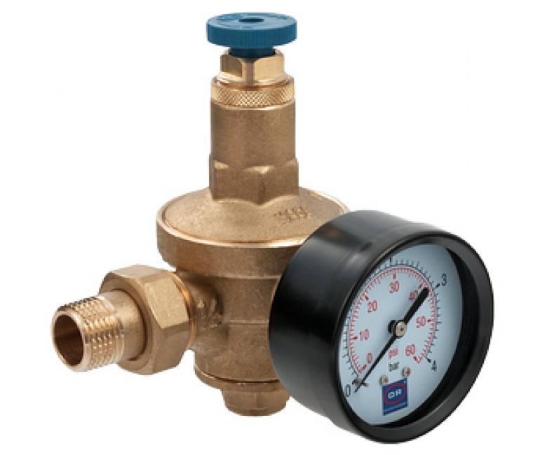
 In the reduction valve of the heating system recharge, a membrane is tested that is testing the pressure of the energy carrier. The required water pressure is set using a spring when the membrane rises and presses on the spiral. With a drop in pressure, the effect on the spring decreases, and the fluid enters the hole that appears.
The make-up device assembly includes elements:
- pressure reducer;
- pressure reducing valve;
- ball valve;
- bypass
- input filter.
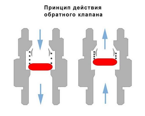
Models of make-up modules are equipped with strainers, check valves, manual cleaning elements. The non-return valve is placed behind the pressure reducing valve and serves to clean the water supply.
Automatic
Automation works according to a simple scheme and does not require external adjustment, except for preliminary settings. The lowest pressure level in the system is programmed when a certain volume of water is lost.
The principle of operation is to automatically operate the valve and start the charge pump for heating. For the pump, the amount of water infused is also determined, which is determined by the amount of energy lost. The valve stops recharging the line when the system is filled to a predetermined rate.
The pressure gauge cuts into the cold water supply pipe, sometimes a liquid pressure control sensor is used in two directions. At this point, a relay is placed, a contactor - all devices are tuned to the operating pressure indicators.
Mechanical
The module has the ability to completely overlap or open, which is important when starting the trunk and filling the system with energy. To speed up the process, a lever is provided.The valve is manually adjusted to the pressure limit when it will operate.
Make-up with mechanics is set in small heating systems, because in them the increase in pressure is clearly determined by the position of the membrane. The lack of energy in the circuit is compensated manually by simply opening the valve on the fluid inlet pipe.
It is important to install a pressure gauge, to which the valves are supplied. Devices without a sensor are cheaper, but you cannot do without it in the heating main.
Mounting Features
The valve is placed on the pipe so that the direction of fluid coincides with the direction of the arrow. The filter plug is directed downward and the set screw should be accessible for use. The dial of the manometer rotates to make it convenient to read the values.
Winding material is used rationally so that excess does not fall into the gearbox lumen. The boiler feed in the form of a valve should not depend on the main loads (compression, torsion, bending, vibration). For this, additional supports or compensators are placed.
The mismatch of the axes of the pipelines should not be more than 3 mm with a length of 1 m. With a greater length, 1 mm is added per linear meter. The make-up circuit is connected to the pipeline not far from the expansion tank.
Calculation of recharge
The calculation of the required volume of added water is carried out in accordance with SNiP 41-02-2003 "Heat Networks".
In closed heating circuits, a coefficient of 0.075 to the total energy source in the networks and pipelines connected to them is used.
The 0.05 factor is applied to the volume to calculate the recharge of sections that are more than 5 km away from the boiler house in open and closed systems.
In open highways, a coefficient of 0.12 is taken to the volume of the average fluid flow to the hot water supply and the actual volume of energy in the pipes is added with a factor of 0.075.
Popular manufacturers
When choosing a valve, attention is paid to the complete set of the module and ease of use. The design and specifications of the make-up device are taken into account. The working mechanism protects the heating system from stopping, manufacturers install filters in the design. The range of working pressure matters, the permissible temperature of heating the energy carrier.
Watts
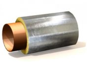
In the brass body is placed a check valve, a shut-off device, a coarse filter, a screw for venting air. The inlet pressure is limited by a threshold of 10 bar, and the output is set in the range of 0.3 - 4 bar. The bimetallic membrane is made of pressed plates with different expansion rates. The deformation of the septum is directly proportional to the change in heating.
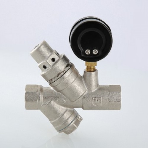
Emmeti
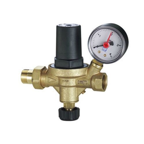
The design includes pressure reducing, shut-off and non-return valves, the closing and opening of which is regulated by a check valve, a socket for mounting the pressure gauge is provided. The backpressure valve prevents hit of an energy carrier in a water supply system. It consumes a maximum of 1.8 m3 of liquid per hour, with a sensitivity of 0.2 bar. The maximum heating of the supply line is set to + 40 ° C, the pressure gauge is designed for a pressure of 0-4 bar.
Valtec
The body is made of brass, the check valve spring, the gearbox and the filter screen are made of stainless steel. The pressure gauge has an accuracy class of 3 and is adjustable in the range of 1 - 10 bar. Filters and manometers are designed to work in the supply line with heating up to + 130 ° C and a pressure at the valve inlet of 16 bar. The output head is selected 2 - 5 bar with a factory parameter of 3 bar.