Uniform heat distribution is one of the defining tasks in the design of a heating system. A number of methods can be used to solve it. However, the most productive is the collector for home-made heating: schemes, varieties and proper installation will help to put this into practice.
Features of collector heating
The main difference between the collector and the traditional method of distribution of the coolant is the separation of flows through several independent channels. In this case, various types of heating collectors are used, differing in configuration and size.
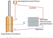
The design of the distribution comb (this is what is sometimes called the welded collector for heating) is quite simple. In a square or round pipe, several pipes are installed that are connected to individual heating circuits. The collector itself is connected to a central pipeline.
In the future, using shut-off valves, you can adjust the level of coolant inflow into individual heat supply circuits. In this case, you can make a distribution heating manifold with your own hands, or purchase an already finished design.
Operational features of heat supply using a distribution comb are as follows:
- Uniform hydraulic and temperature distribution. Even the simplest ring heating collector for two or four circuits can effectively stabilize the system;
- Adjustment of heat supply operation modes. This is done using special components - flow meters, mixing units and temperature controllers. But before installing them, the correct calculation of the collector for heating is necessary;
- Maintainability of the system. To carry out repair or maintenance work, you do not need to turn off all heat supply in the house. It is enough to pre-install a heating collector with flow meters and use shut-off valves to block the flow of hot water into a certain circuit.
But heating with collectors has a number of disadvantages. First of all, it is an increased consumption of pipes. The increase in hydraulic resistance is compensated by the installation of a circulation pump. It is mounted on each distribution comb in the system. Also, a steel manifold for heating can only be used for closed systems.
The collector distribution of the coolant is relevant for houses with a large area. In this way, the gradual cooling of hot water, which is typical for classic two-pipe and single-pipe schemes, is compensated.
Types of collectors for heating
Before you make a collector of a heating system with your own hands, you need to determine its functional load. This design can be installed in several places of heat supply. Its configuration, overall dimensions and level of automation will depend on this.
Before assembling the heating collector, it is calculated, the installation location is determined. In fact, the system requires two designs. The comb from the supply pipe distributes the hot fluid along the heating circuits. Return polypropylene collectors for heating are the point of collection of cooled water for its further transportation to the boiler heat exchanger.
A home-made heating collector may be needed in two cases - for a water floor heating system or in the organization of traditional heat supply with radiators. They differ in size and configuration:
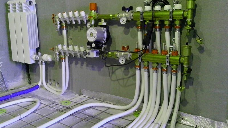
- Rows for the boiler room. For this, welded collectors are used for heating, made of pipes of large diameter up to 100 mm. Circulating pumps and control valves are mounted in the feed comb. To complete the reverse ring heating manifold, shut-off ball valves are used;
- Combs for underfloor heating. In addition to the above components, a mixing unit is used. It allows you to save coolant consumption. Additionally, the use of a heating manifold with flow meters is recommended.
Each option has its own installation scheme and operating rules. Correct installation of the heating collector is carried out only after a detailed calculation of all parameters of the heat supply. Another difference is the number of installed circulation pumps. In the comb for the boiler room, they complete each circuit. For a local view of heating collectors in the underfloor heating system, only one pump is installed.
Crest material may differ from piping. Correct connection of the heating collector in this case is done using special adapters.
Calculation of the heating collector
Before self-production of the distribution comb, it is necessary to perform calculations of its main parameters. These include the length, cross-section of the connecting pipe and the number of heat supply circuits. In this case, the calculation of the heating distribution manifold can be done independently, or using specialized programs.
The main condition is to maintain the hydraulic balance in the structure. In the DIY heating manifold, the throughput of the connected pipe should be equal to the sum of the same characteristics of the heating circuits. In practice, this can be achieved by summing the cross-section of the nozzles. The result should be equal to the cross section of the main pipe, which is connected to the supply line. In this way, the likelihood of system imbalance can be reduced.
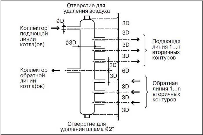
To optimize the place, they often make manifolds of the heating system with their own hands in a single building. This reduces the complexity of the work, and also contributes to a better functioning of the heat supply. However, the minimum distance between the supply and return pipes should be six diameters.
For further calculations of the collector for heating, you can use the rules of 3 diameters. It consists in the following conditions:
- The distance between the inlet outlet groups of the comb should be 6 diameters;
- The cross section of a steel or polypropylene collector for heating is equal to 3 diameters of a pipe connected to the system;
- The remoteness of the heating circuits is equal to 3 diameters;
It is also important to choose the right circulation pump. First of all, it concerns its performance. Before installing the heating collector, the specific water flow in the system is calculated and, according to the results obtained, a pump is selected. For complex circuits with several collectors, this procedure should be done for each circuit separately and for the entire system as a whole.
For the manufacture of a home-made heating collector, you can use pipes with a square, rectangular or round cross-section. This will not affect the operation of the structure, and will not increase the hydraulic resistance. It is compensated by the operation of the circulation pump.
Complete set of collectors of heating
After performing the calculation, it is necessary to select the appropriate equipment for the distribution comb.In order to properly assemble the heating collector, you must take care of the required elements in advance.
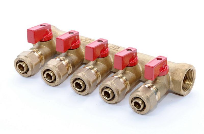
In the minimum set for a steel heating manifold, it is enough to install shutoff valves. But in this case there will be difficulties with adjusting the power of the individual heating circuits.
Therefore, cranes with a rod are mounted in the feed comb for the boiler room, with which you can smoothly control the flow of coolant. Additionally, flow meters are mounted on the return comb.
When calculating the distribution manifold of heating for the water floor, another configuration scheme is taken into account. It should consist of the following elements:
- Control valve. Are mounted on branch pipes of highways. With its help, you can partially or completely leave the influx of hot water. In the manufacture of a collector of a heat supply system with their own hands, it is recommended to use automatic models similar to temperature controllers;
- Flow meters. These components are mounted on the back comb. Their functions are similar to control valves. The difference in the work of the heat supply collector with flow meters is to limit the flow of coolant into the return pipe;
- Mixing unit. Mandatory component for water underfloor heating. It mixes the flows of hot and cooled water, thereby optimizing the temperature regime of the heat supply.
Despite the differences, all types of collectors for heating have one common property - they ensure stable operation of the system. You can make such a design yourself, or by purchasing a ready-made factory model. The latter option is acceptable if the ring collector of heat supply is necessary for the underfloor heating system. When organizing heating using combs, it is best to make them yourself. Thus, the design can be adapted to specific heat supply parameters.
During assembly of the heating manifold, servos can be used that are connected to the electronic control unit. With their help, the system will work automatically.
Self-made collector
For the manufacture of a distribution comb, a scheme is drawn up in which all the materials used are taken into account. The rules for calculating the size of the structure were mentioned above. But besides them, it should be borne in mind that the material for making the distribution manifold of heat supply with your own hands will have to withstand all types of load - temperature and pressure.
As a starting material, it is best to use a square tube. This applies to steel manifolds for heat supply. It is easier to process - the complexity of the installation process of the pipes decreases. The form will not affect the operation of the heating system.
It is important only to correctly calculate the collector for a particular heating, taking into account all factors. For the traditional scheme, it is best to make steel structures, since they have a long service life and are less prone to breakage than polymer analogues. In water-heated floors, both polypropylene collectors for heat supply and steel are successfully used.
The order of manufacture of the distribution comb.
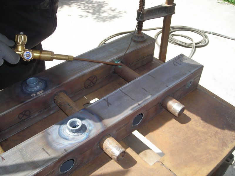
- Blank cutting. First of all, it is necessary to make the main body and pipes for it.
- Assembly assembly. To make a steel home-made collector, a welding machine is needed in the heating system. The connection of the nozzles in a polypropylene analogue is performed using temperature welding.
- Design check. To do this, fill it with water and create the maximum allowable pressure that can be in the heating. Leakage is not allowed.
Often refuse to make a welded collector for heat supply on their own. This is due to the lack of an appropriate tool. An alternative manufacturing method is the purchase of individual components. It is best to choose items from one manufacturer. Thus, it is possible to ensure reliable operation of the structure.
In the manufacture of a polypropylene comb, it is desirable to use large diameter pipes. They must have a reinforcing layer. Otherwise, temperature deformation is possible.
Installation of the collector in the heating system
Before installing the heating manifold, its tightness and reliability are checked again. Installation is carried out according to a pre-compiled scheme. The conditions for connecting the structure to the heating system depend on the material used to make the comb.

It is important not only to make the design correctly, but also to make a competent connection to the heating collector. Installation technology depends on the type of equipment used. In addition to observing the level during installation, the following nuances must be considered:
- Electric and gas boilers. They will connect to the upper or lower nozzles;
- Circulation pump. It is installed only from the end of the structure;
- Heating circuits. Connect at the top or bottom of the collector;
- Indirect heating tanks and solid fuel boilers are installed only in the side.
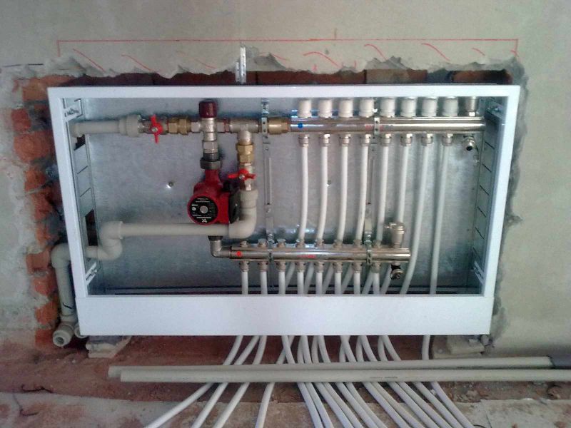
For a warm water floor system, a protective box must be provided in which the collector will be located. Without it, the likelihood of damage to individual components increases.
It should be remembered that even with small irregularities during the manufacture of the collector, the chance of improper operation of the heating system increases. Therefore, after installing the comb, it is recommended to conduct a series of trial runs of heating in order to timely identify obvious and hidden system flaws.
In the video, you can see an example of a homemade heating collector: