An electric current generator is a device designed to convert non-electric types of energy (chemical, mechanical, thermal) into electrical energy. Moreover, its design is based on the use of the principle of electromagnetic induction.
The principle of operation and the device of the simplest alternator
Electromagnetic induction is a phenomenon that was discovered in 1831 by the British physicist Michael Faraday (1791-1867), who discovered that when a time-varying magnetic flux passes through a closed conductive circuit, an electric current arises in the latter. It is this principle that underlies any generator.
In practice, the principle of electromagnetic induction is implemented as follows: an electric current arises in a closed frame (rotor) when it intersects with a rotating magnetic field, formed depending on the purpose and design of the generator by permanent magnets or special excitation windings. When the frame rotates, the magnitude of the magnetic flux changes. The faster it rotates, the higher the output voltage.
In 1827, this effect was discovered and used to create the original model of an electric current generator by the Hungarian physicist Agnos Istvan Jedlik (1800-1895). However, considering it famous, the scientist did not patent his discovery, and announced the creation of the first dynamo only in 1850.
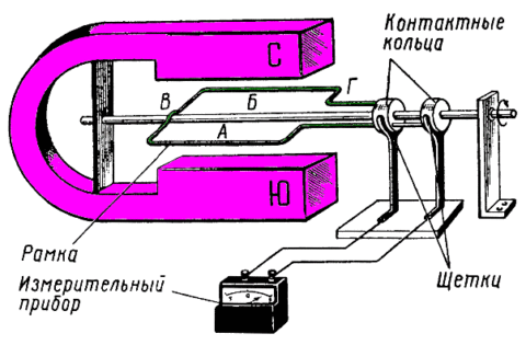
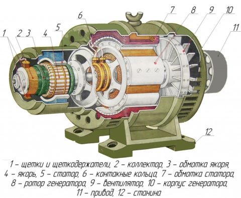
To remove electric current, the frame is equipped with a current collector, which turns it into a closed loop and provides constant contact of the rotating frame with stationary elements of the generator. Spring-loaded brushes are pressed against the collector rings and thus the electric current is supplied to the output terminals of the generator.
Rotating, the halves of the frame pass sequentially near the poles of the magnet. In this case, a cyclic change in the direction of movement of the emerging current occurs - at each pole the current moves in one direction.
Depending on the design of the collector, the generator can generate both direct and alternating current.
- In DC generators, for each half of the winding in the collector node, there are isolated rings from each other. Due to the fact that these half rings are constantly changing brushes, the current does not change its direction, but simply pulsates.
- In alternators, the ends of the frame are tied to slip rings and this whole structure rotates around its axis. When rotating the frame, brushes, each of which is closely adjacent to its ring, provide a reliable down conductor. In this case, a cyclic change of position of the brushes does not occur.
The rotating part of the generator is called the rotor, and the stationary part is called the stator.
The principle of operation of alternating and direct current generators is identical. They differ among themselves in the design of slip rings located on a rotating rotor and the configuration of the windings.
In alternating current generators, an original technical solution is often used, based on the fact that the EMF appears in the conductor not only when it rotates in a magnetic field, but also in the case when the magnetic field itself rotates relative to a stationary conductor.
This effect is widely used by developers who place electric or permanent magnets on a rotating rotor. In this case, the voltage is removed from the stationary mounted winding, which makes it possible to get rid of the complex designs of collector assemblies.
AC generators
 A huge number of the most diverse AC generators are produced. They can be classified by the following parameters:
- constructive design;
- excitation method;
- number of phases.
By the method of excitation to the consumer, aggregates can be found:
- with independent excitation - the excitation winding is supplied with direct current from an independent power source;
- with self-excitation - a rectified current from the generator itself is supplied to the excitation winding;
- with excitation from permanent magnets - no excitation winding;
- with excitation from the pathogen - a low-power DC generator, "sitting" on the same shaft with the served generator.
By the number of phases, electric generators are:
- single phase;
- two-phase;
- three phase.
In practice, three-phase alternators are most often found. This is due to a number of advantages characteristic of this type of aggregates:
- obtaining an economic effect in the development of long-distance power transmission systems - reducing the material consumption of transformer devices and power wires; This contributes to the presence of a circular magnetic field;
- increased operational resource, which ensures the balance of the system;
- simultaneous use of linear and phase voltage.
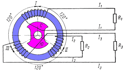
Structurally, a three-phase electric generator has three independent windings located in the stator around the circumference with an offset of 120 ° relative to each other. In addition, each winding is a single-phase generator, which is capable of supplying alternating voltage to the consumer R. Such a single winding is called the "phase". Phase windings can be interconnected by a "triangle" or "star".
There are other schemes for connecting the windings, for example, the six-wire Tesla system or the Slavyanka connection (a combination of six windings in the form of one “star” and one “triangle”), but they were not widely used.
The role of the frame in devices generating alternating current is played by an electromagnet, which, rotating, shifts the EMF variables induced in the windings by a third of a cycle relative to each other.
Among the many alternators, there are two main types of their design: synchronous and asynchronous. Recently, given the large number of complex electronic devices controlled by microprocessors, a new type of electric generator has appeared - inverter.
Synchronous Power Generators
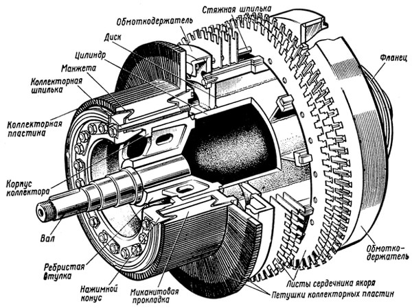
A synchronous alternator consists of two parts - a movable rotor and a fixed stator.
When the rotor rotates, which is an electromagnet with a core and an excitation winding, connected to an external power source using a brush mechanism, an EMF is induced in the stator winding, which is fed to the output terminals of the generator. This design eliminates the need for sliding contacts, which greatly simplifies the design of the unit. Initially, the magnetic flux is excited from a third-party exciter mounted on a common shaft and connected to the system using a coupling.
In low-power synchronous generators, the field winding is powered by a rectified current. In this case, the electric circuit is formed due to the activation of transformers included in the load circuit. A semiconductor rectifier is also included. The main electrical circuit includes:
- field winding;
- adjusting rheostat.
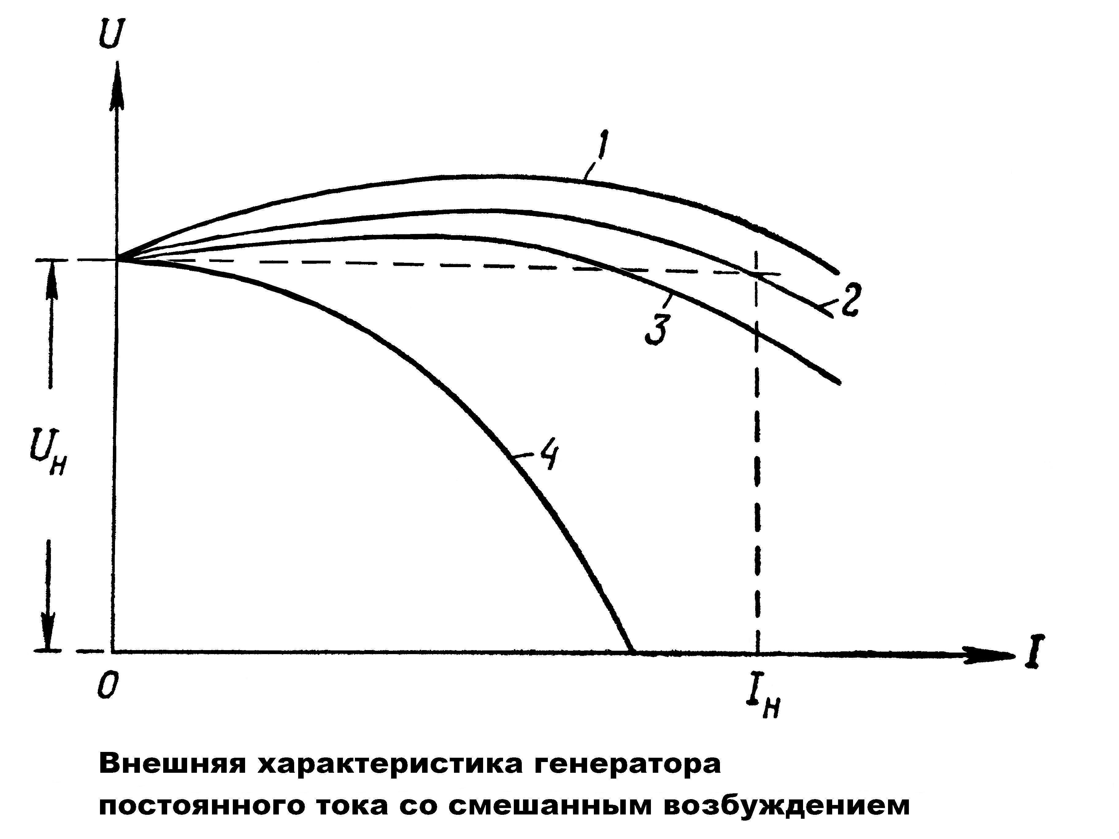
The main feature of the synchronous generator is that the frequency of the generated electric current is proportional to the rotor speed.
Asynchronous Power Generators
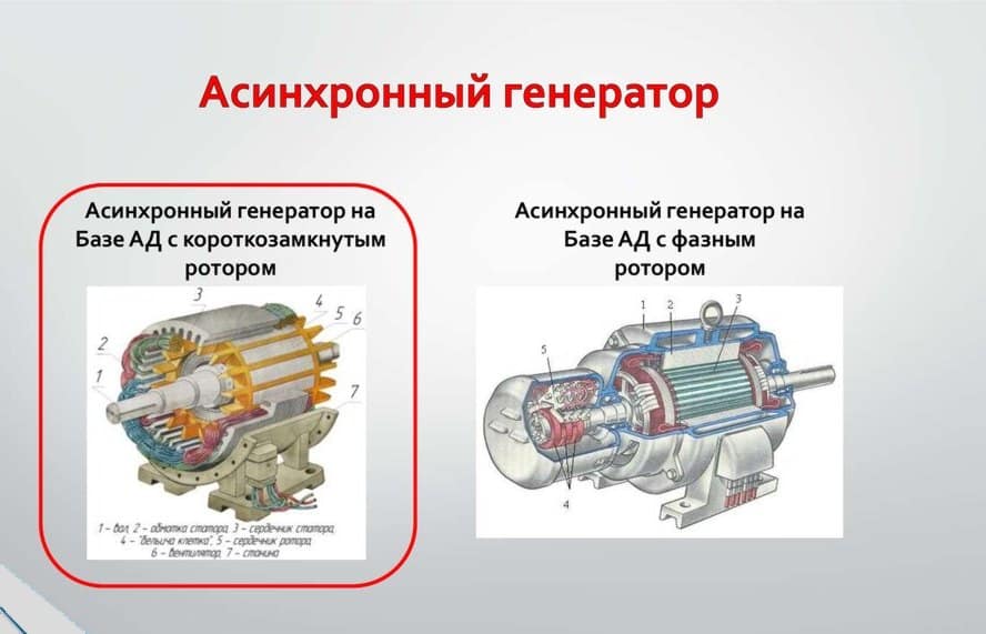 An asynchronous alternator differs from a synchronous one in the absence of a rigid connection between the rotor speeds and the induced emf. The difference between these parameters is called “slip”. There is an air gap between the rotor and the stator of the asynchronous generator. At the same time, the braking torque that occurs when the load is connected and prevents the rotation of the rotor affects the frequency of the generated EMF. Therefore, electricity in asynchronous generators is generated at an increased rotor speed.
The design of asynchronous generators is simple, but it has the worst technical characteristics compared to synchronous units - the error in frequency can reach 4%, and in voltage up to 10%. In addition, asynchronous generators are critical to the inrush current. Therefore, it is recommended to operate them together with stabilizers, and in some cases, for example, for a smooth start of the electric motor, a frequency converter may be needed.
Inverter Generators
An inverter generator is a conventional asynchronous generator, at the output of which an additional stabilizer of output parameters is installed.
It works as follows: the voltage generated by an asynchronous generator goes to the inverter, where it is first rectified, and then pulses of a given frequency and duty cycle are formed from the obtained constant voltage. At the output of the device, these pulses are converted to a sinusoidal voltage with almost perfect technical characteristics.
Alternator drive
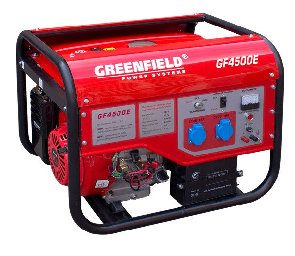
In domestic conditions, the generator rotor is driven by internal combustion engines (ICE) operating on fuels such as gasoline or diesel. At the same time, the operational life of gasoline generators equipped with push-pull ICEs is about 500 hours per year (no more than 4 hours per day); four-stroke ICE reaches 5000 hours per year.
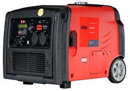
It is advisable to use gasoline electric generators for short power outages and / or for going out into the countryside.
Generators running on diesel fuel are characterized by high power and much more durable gasoline. Among them there are models with air and liquid cooling. Air-cooled units are recommended for use in places where electricity is often turned off for a long time.
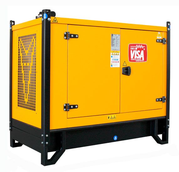
Using such household appliances is extremely simple - you need to fill the fuel in the tank, turn the key to start the engine and connect the load. Their control panel is equipped with all the necessary and intuitive inscriptions and symbols.
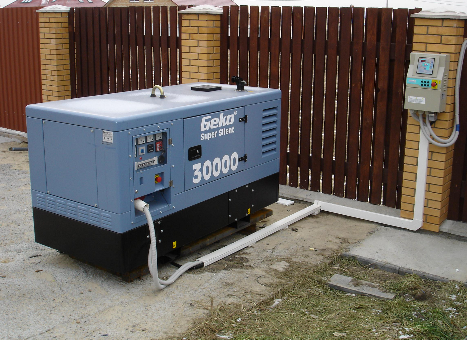
Liquid-cooled diesel generators are devices in a completely different category. They are able to work for days and are used mainly in enterprises as backup power sources.
Industrial generators designed to generate alternating current and supply it to consumers over long distances using high-voltage power lines (power lines) operate by activating hydraulic or steam turbines. In such units, the rotor mechanism is connected directly to the turbine wheel.
Turbine generators are characterized by high power (up to 100,000 kW) and are capable of generating alternating current with voltage up to 16 kV. The length and diameter of their rotor can reach 6.5 and 15 meters, respectively, and the rotation speed of the latter is in the range of 1500 ... 3000 rpm.Install such units in separate rooms on specially prepared concrete substrates.
Options and capabilities of household electric generators
For ease of use, manufacturers equip their products with a number of useful options, among which are:
- device for automatic start of the unit during a power outage;
- the presence of a built-in RCD, disconnecting the device from the mains during breakdown of insulation and the appearance of a leakage current;
- control parameters and display them on the display;
- overload protection.
When a load is connected to an electric generator, the value of which will be lower than the rated one, the unit will begin to “eat up” part of the liquid fuel for nothing, without fully utilizing its capabilities.
It will not be superfluous to have in the delivery set a special silencing casing, an increased fuel tank, a casing protecting the unit from exposure to low temperature, etc.
Installation Features
A potential owner of an alternator must take care of the preparation of the installation site before purchasing. Regardless of where such a unit will be installed, indoors or outdoors, it will require a flat and solid platform. Installing an electric generator on an uneven site will lead to an increase in vibration, which will accelerate the wear of parts and can provoke the failure of an expensive device.
When installing the generator in a room, it is important to provide for the presence of exhaust ventilation. In addition, during the operation of the unit, it is recommended to leave the room door open, which in turn will require the installation of a grille in the doorway that blocks outsiders, and most importantly children, from accessing the danger zone.
The electric generator is connected to the mains in strict accordance with the requirements set forth in the operating instructions. In this case, the electric cable must be connected after the introductory machine and electric meter.