To control various electronic equipment, a device is required that is distinguished by its miniature size and a high degree of reliability. These devices include solid state DC and AC relays. They found their application in domestic and industrial conditions. Relays can be independently assembled and installed with your own hands without any difficulties. The only criterion that prevents the wide distribution of the device is its cost. Before using a solid-state relay, you need to understand its parameters, the principle of operation, design.
Principle of operation
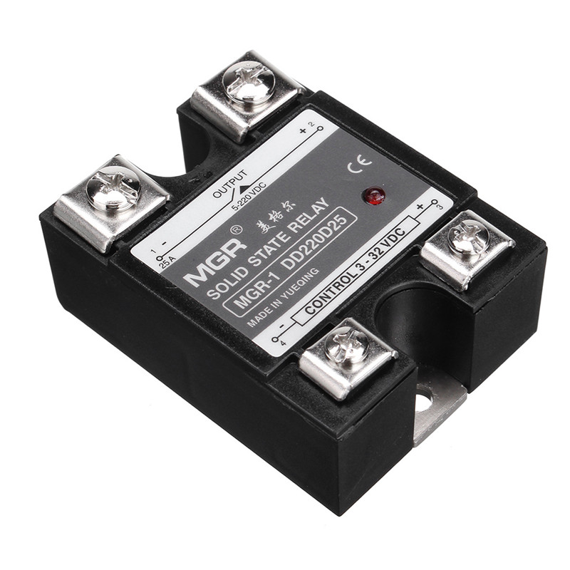
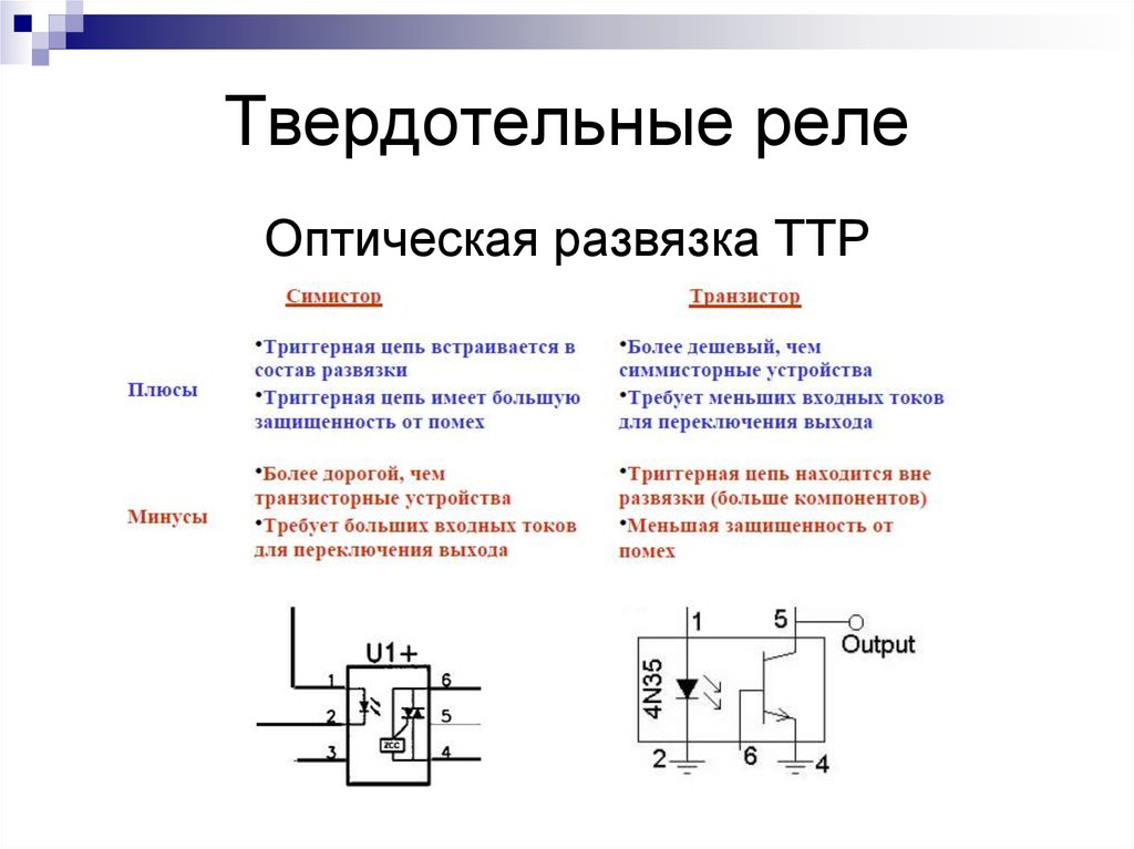
A solid state relay is a modular semiconductor device used to close and open electrical networks. It is presented in the form of transistors, triacs, thyristors. Solid state relays are also called SSR (solid state relay).
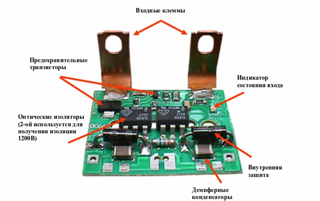
The main components of which the relay consists:
- input node;
- circuit breakers;
- trigger chain;
- denouement;
- switching unit;
- protective circuit;
- output node.
Most solid-state relays are used for automation connected to a 20-480 Volt mains.
The principle of operation of the device is simple. The relay case includes two contacts and two control wires. Their number may vary depending on the phases that have been connected. Under the action of voltage, the main load is switched.
When working with relays, you need to consider that under high voltages there is a risk of small leakage currents that can harm the equipment. This is due to the fact that a small resistance remains in the relay.
Famous models
Key features depend on many factors. Popular domestic models manufactured by KIPprbor, Proton, Cosmo include:
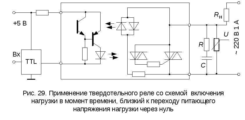
- TM-O. Devices with an embedded "zero" circuit through which the phase transition passes.
- TS. Models that turn off at any given time.
- The most popular and used are TMV, TSB, TSM, TMB, TSA. They have an output RC circuit.
- TS / TM - power. Currents reach 25 mA.
- TSA, TMA - are used in sensitive devices.
- TSB, TMB - low-voltage models. Voltage does not exceed 30 V.
- TSV, TMV - high voltage. Voltage reaches 280 V.
Foreign analogues include products manufactured by Carlo Gavazzi, Gefran, CPC.
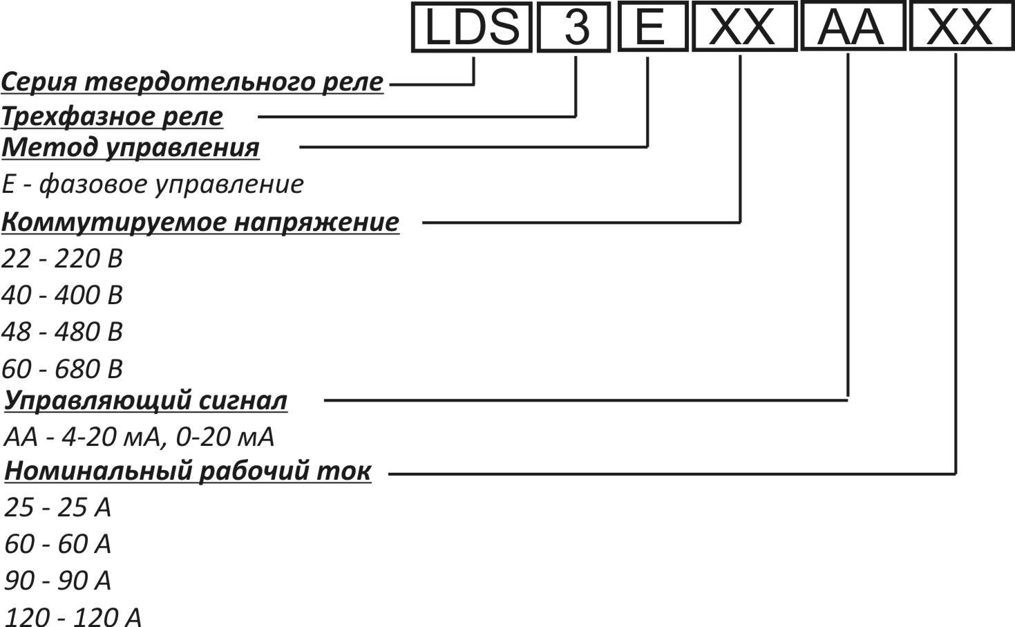
Decryption
SSR, TSR models (single-phase and three-phase, respectively) are the most popular. Their resistance is 50 megohms or more at a voltage of 500 V.
The designation is written as SSR -40 D A H. SSR or TSR indicates the number of phases. 40 - load in Amperes. The letter indicates the signal at the input (L 4-20 mA, D - 3-32 V at constant current, V - alternating resistance, A - 80-250 V at alternating current). The next letter is the input voltage (A - alternating, D - constant). The last letter is the range of output voltages (N - 90-480 V, no letter - 24-380 V).
Features of working with the device
When working with a solid state relay 220v (control 220), you must adhere to the following rules:
- The connection must be screwed. It is reliable enough. Spike parts are not needed, twisting is prohibited.
- Do not allow dust, water or metal objects to enter the relay. They lead to component failure.
- Do not use unacceptable external influences on the housing. These include flooding, shock, vibration, falling.
- Do not touch the device during operation.The case heats up, which can cause a person to burn.
- Do not install the relay near flammable objects.
- Before connecting the circuit, make sure that the assembled connections are correct.
- When the case is heated above 60 degrees, the installation of additional cooling with radiators is required.
- A short circuit at the output must not be allowed.
Subject to the requirements for operation, the relay will perform its work reliably and efficiently throughout the declared term.
Advantages and disadvantages
 Solid state relays have a number of positive qualities over electromechanical counterparts. These include:
- Durability. A semiconductor device can withstand up to tens of thousands of on and off cycles.
- It creates a high-quality connection.
- Competent load control.
- High performance.
- Lack of electromagnetic interference in a closed network.
- Quick response.
- Silent work.
- Miniature sizes.
- Lack of bounce of contacts.
- High performance.
- Possibility of a smooth transition between AC and DC networks. Depends on the power and type of device.
- Wide range of applications.
- Withstands overloads in 2000.
- Protection against sudden and large surges in voltage and current.
There are a number of disadvantages, because of which the electromechanical relay can be more profitable to use. First of all, this is the high cost of the product and the complexity of its purchase. Solid-state relays can only be purchased at a professional specialized store for electronic components. Difficulties also arise during primary switching - high current surges can appear. Microcurrents that occur during operation also adversely affect the relay.
Operational requirements are superimposed on the operation of the device - the room must have a normal level of dust and humidity. Optimum values can be found in the relay documentation.
Solid state relays cannot work with devices whose voltage exceeds 0.5 kV. Increasing recommended values may result in molten contacts.
Areas of use
Despite the high price, solid-state relays are actively used in various fields. They successfully cope with the following tasks:
- Temperature control with the help of PETN.
- Maintaining the right temperature in technological processes.
- Switching control circuits.
- Replacement contactless starters.
- Electric motor control.
- Transformer heating control.
- Backlight leveling.
In each case, a specific type of relay is used.
Solid State Relay Classification
Solid state solid state relays can be classified according to different indicators. According to the features of the control and switched voltage, there are:
- Solid State Relays They are used in DC circuits with power from 3 to 32 watts. They are distinguished by high specific characteristics, the presence of LED indicators, and reliability. The operating temperature range is wide enough and ranges from -30 to +70 degrees.
- AC relay. They are characterized by low level of electromagnetic interference, lack of noise, low power consumption. The range of operating powers is from 90 to 250 watts.
- Manual Relays Using such devices, you can independently adjust the operating mode.
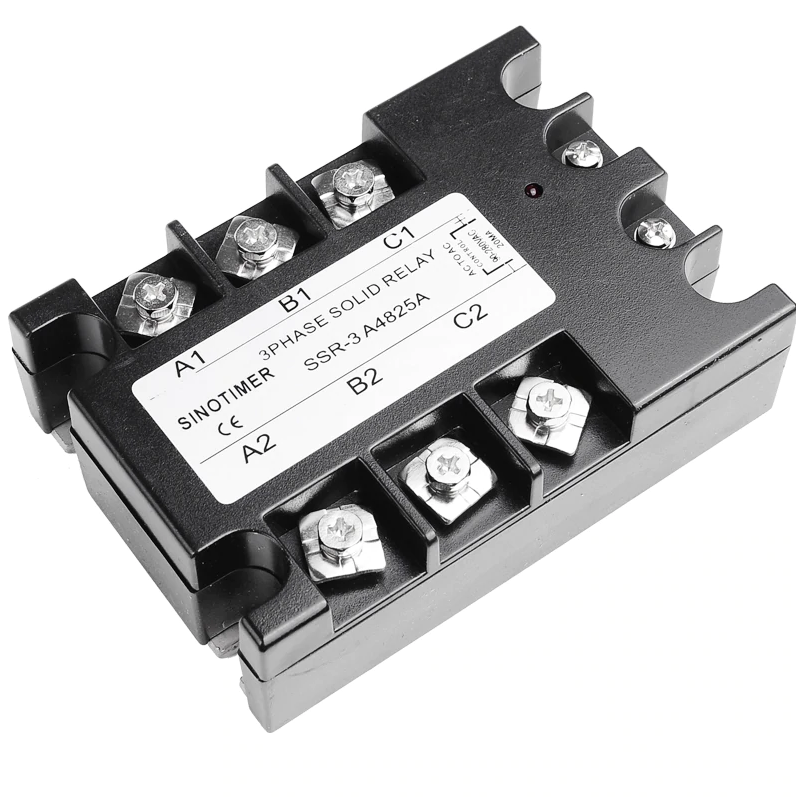
According to the type of voltage, single-phase and three-phase relays are distinguished. Single-phase devices are used in networks with a current strength of 100 to 120 A or from 100 to 500 A. In them, control is carried out by receiving an analog signal and a variable resistor. Three-phase relays are used for switching on three phases simultaneously. The current strength is 10-120 A. Three-phase models last longer than single-phase ones.
In a separate group of three-phase solid-state relays, reversible devices are distinguished.They are distinguished by marking and contactless connection. The main function is the reliable switching of each circuit individually. They protect the circuit from false positives. Found the main application in induction motors. To operate the relay, a fuse or varistor must be installed.
According to the switching method, relays are classified as follows:
- capacitive or reductive type devices, as well as weak induction devices;
- with random or instant operation;
- with phase control.
By design, it is possible to distinguish models that are installed on a DIN rail and on a special bracket of a transition type.
Selection tips
You can buy solid state relays only in a specialized store of electronic equipment. Experienced specialists will help you choose the best device for certain purposes. The following factors affect the cost of a product:
- type of relay;
- the presence of locking mechanisms;
- case material;
- on time;
- manufacturer and country of manufacture;
- power;
- necessary energy;
- dimensions.
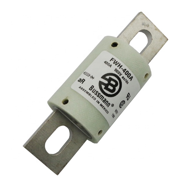
When buying, it is important to consider that there should be a margin of power that exceeds the working one by several times. This will protect the relay from damage. Special fuses are also used. The most reliable include:
- G R - are used in a wide range of loads, are characterized by high speed.
- G S - operate in the entire range of currents. Reliably protect the device from exceeding the load of the mains.
- A R - protect components of the semiconductor device from short circuit.
Such devices provide high protection against breakdowns. Their cost is comparable to the price of the relay itself. Fuses of classes B, C, D have lower protective properties and, accordingly, lower cost.
For reliable and stable operation of the relay, you need to choose a cooling radiator. This is especially true when the temperature exceeds 60 degrees. The current reserve for a conventional relay should exceed the operating currents by 3-4 times. When working with induction motors, this figure should increase to 8-9 times.
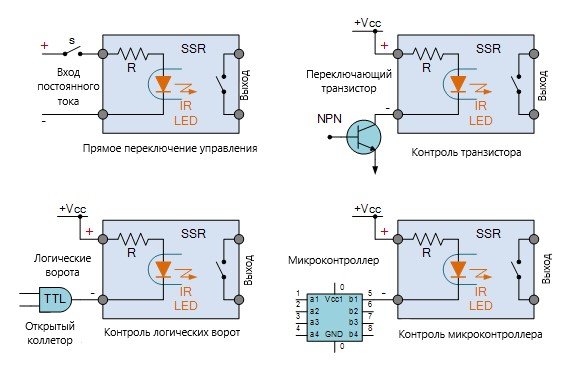
Wiring diagrams
 There are various ways to connect solid state semiconductors. They depend on the features of the connected load. Additionally, various controls may be included in the circuit.
The most used schemes include:
- Normally open. The load is energized with a control signal.
- Normally closed. The load is energized in the absence of a control signal.
- The control and load voltage are equal. It is used for work in direct and alternating current networks.
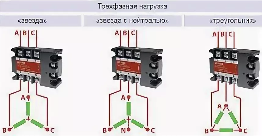
- Three phase. It can be connected in different ways - “star”, “triangle”, star with neutral. ”
- Reversible. A kind of three-phase relay. Includes 2 control loops.
Before assembling the diagram, it must be drawn on paper.
Connection to the network is through starters or contacts. When using a three-phase relay, all 3 phases must be connected to the corresponding terminals located on top of the device. The upper phase contacts are marked with the letters A, B C, zero - N.
The device also has lower terminals marked with the numbers 1, 2, 3. They are connected using the following algorithm:
- 1 - to the output of the coil in the contactor.
- 3 - to any phase that goes around the relay.
- 2 - to network zero.
Power elements are connected as follows: live phases must be connected to the corresponding terminals on the contactor; load conductors - to the output of the contactor; zeros are combined on a common bus in the junction box.
Relay settings will be considered on the example of VP 380 A:
- Connect the device to the network.
- Look at the display. If there is no voltage, the numbers will flash. The appearance of dashes indicates a change in phase rotation or the absence of one of them.
In the normal state of the mains, after approximately 15 seconds, contacts 1 and 3 should close, supplying power to the coil and to the network.
If the connection is incorrect, the screen will blink. Then you need to check its correctness. You can set the necessary settings using the buttons on the case. Buttons with triangles are responsible for setting the desired limits.