For protection of household or industrial equipment with electric motors from overheating, forced cooling devices are used. If they are not enough, you can optionally connect a thermal relay. The device protects the network from overload, and the equipment from failure and expensive repairs.
Reasons for using protective devices
Network overload leads to an increase in the temperature of the power line, causing complex breakdowns and emergency situations. The heat device in this case creates the conditions for turning off the electricity.
After a fault signal is received, it opens the circuit, and current surges do not affect the motor.
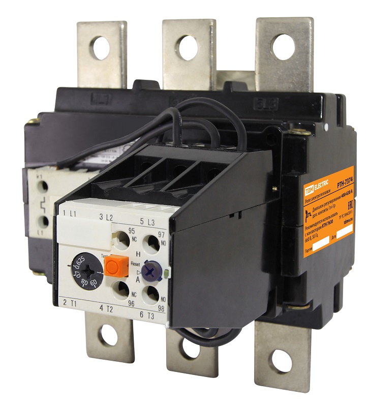
The thermal type relay is suitable for independent connection, differs in compactness, simplicity of design.
Before you start using the device, you need to understand its design and features.
The principle of operation and design of the thermal relay
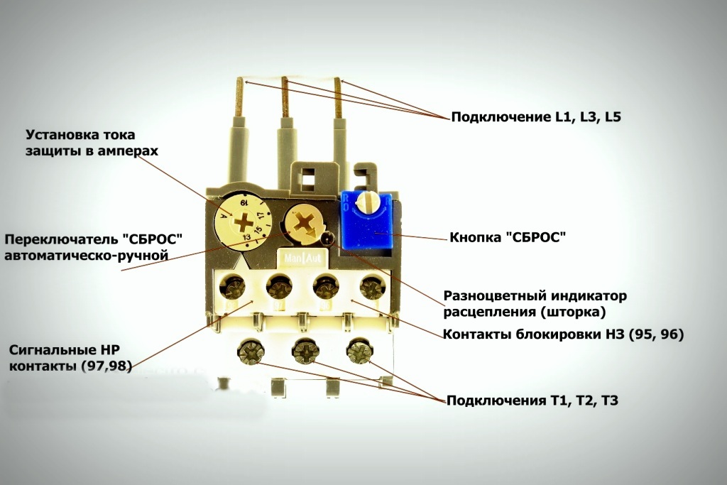
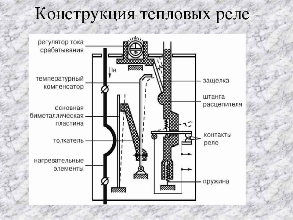 Regardless of the type of TR, they have the following device:
- sensitive bimetallic plate - made of two metals with different expansion coefficients;
- heating coil;
- mechanism of levers and springs;
- contacts - normally open and permanently closed - are able to change state when protection is triggered.
The action of the device is based on the deflection of the plate to the metal with a lower coefficient of thermal expansion at the time of overload. A force is exerted on the contact system - the equipment stops. After cooling, the plate returns to its original position.
Since the operation of the relay depends on the room temperature or additional heating, the counterweight principle is used in the design. For its implementation, an auxiliary plate of a temperature compensator with adjustment is used. It can bend in the opposite direction.
The current is checked by a special transformer. After processing the data and exceeding the nominal value above the setpoint, a pulse is applied to the shutdown mechanism. The external contactor opens, the load is blocked. The device is installed on a magnetic starter.
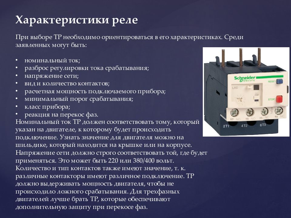
The main characteristics of the current relay
 The main characteristic of the device is the dependence of the response time on the magnitude of the current flow. If there is a denomination, the maximum duration of the generation is infinite. An increase in performance leads to a break in insulation.
The optimal load on the motor should be at least 1.2-1.3 seconds in conditions of 30% overload. If the indicator is greater, the winding or the entire motor heats up. The malfunction is eliminated only after a complete replacement of equipment.
The relay voltage is selected in accordance with the network parameters - 220 or 380 V. Normal motor protection is possible only when choosing a relay that prevents phase distortion.
The current rating can be viewed on the housing strip.
The main types of relays
The compatibility of the relay device with a specific motor depends on its type. Manufacturers produce:
- TRP. A single pole device with a combi heating system that protects asynchronous motors. Suitable for mains with direct current not exceeding 440 V, insensitive to shocks.
- RTL Prevents engine malfunction under conditions of phase failure, current asymmetry and overload, prolonged start-up, jamming. It is mounted on a din-rail separately or together with a starter.
- PTTThe main purpose of the devices is to prevent a prolonged start, overload, phase imbalance of asynchronous motors with squirrel cage rotors.
- TRN. Two-phase switch for controlling the start and functionality of the engine. Suitable for AC mains, contacts return to their original position manually.
- RTI. Thermal RTI-relay is characterized by minimal power consumption, compatible with circuit breakers or fuses. Installation is made on a special contactor.
- Solid state. Compact devices without active nodes. The principle of their functionality is to check the current of operation and start-up, to determine the average engine temperature. Installed in hazardous areas.
- RTK. A launcher that monitors the temperature inside the equipment enclosure. It is involved in circuits with a relay part of a complete set of automation.
All devices only prevent emergency situations, and do not protect the network from short circuits.
Connection, adjustment and designation of TP
 It is necessary to install an electrothermal relay with a magnetic starter that connects and starts the engine. As a stand-alone device, the device is placed on a din rail or mounting plate.
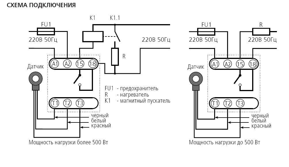
Device connection diagram
Connection diagrams of starters with thermal types of relays depend on the type of device:
- Serial connection with a motor winding or starter coil to a normally open contact (NC). An item works if you connect it to the stop key. The system is used when it is necessary to equip the engine with alarm protection. The relay is placed after the starting contactors, but in front of the motor, then the NC contact is connected.
- Starter zero gap with normally closed contact. The circuit is convenient and practical - zero can be connected to the TP terminal, a jumper to the starter coil pops up from the second terminal. At the moment of operation of the relay there is a gap of zero and de-energizing the starter.
- Reversible circuit. The control circuit contains a normally closed and three power contacts. The electric motor is powered through the latter. When the protective mode is activated, the starter is de-energized and the motor stops.
Regardless of the scheme, to stop the equipment, press the Stop button.
Adjustment procedure
The device is configured on specialized stands with a low-power load transformer. The heating units are connected to its secondary mechanisms, and the voltage is controlled by an autotransformer. The current load limit is regulated by an ammeter connected via a secondary circuit.
Verification is performed as follows:
- Turn the transformer handle to the zero position with voltage applied. Then select the load current with a pen and check the response time of the relay from the moment the lamp goes out with a stopwatch. Norm - 140-150 sec at a current of 1.5 A.
- Setting the current rating. It is produced when the current rating of the heater does not match the rating of the motor. The limit of adjustment is 0.75 - 1.25 of the heater rating.
- Setting the current setting.
For the last action, you need to calculate:
- determine the correction for the rated current without temperature compensation according to the formula ± E1 = (Inom-Io) / СIо. Io - current of zero setting WITH - the division price of the eccentric (C = 0.05 for open models and C = 0.055 for closed);
- calculate correction based on ambient temperature E2 = (t - 30) / 10where t - temperature;
- calculate the total correction by adding the obtained values;
- round the result up or down, move the clown.
This method of adjustment is suitable for devices such as TRN and TRP with indicators similar to average.
Manual adjustment
The thermal relay can be adjusted manually. The value of the tripping current can be set in the range from 20 to 30% of the nominal.The user will need to smoothly move the lever to change the bend of the bimetal plate. The trip current is also regulated after replacing the thermal assembly.
Modern switches are equipped with a test button to search for damage without using a stand. Using the reset key, you can reset the settings in automatic or manual mode. An indicator is used to track the status of the device.
Thermal relay marking
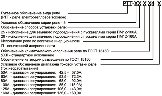
The designation of the device takes the form of letters and numbers, depending on the manufacturer. Most often, marking is made on the basis of an abbreviated name, as well as:
- setting current parameters - is written in brackets in numbers;
- letter designation;
- climatic modification in the form of a range;
- current rating - numbers are used (1 - up to 25 A, 2 - up to 100 A, 3 - up to 510 A);
- device features - compatibility with direct and alternating current circuit, mono-and bistable devices, with acceleration or deceleration of on / off, with or without winding.
All designations are registered in the relay passport.
Features of choosing a thermal relay
The selection of TP should begin by studying the instructions. The technical document of the device contains the following information:
- connection of load current and operation period;
- start state - cooling or overheating;
- rated load of the electric motor - the optimal overload indicator is 20-30%;
- constant load time - from 5 to 10 minutes;
- period of continuous load - from 40 minutes to 1 hour;
- dependence of plate heating on air temperature.
If the temperature deviates from the indicated temperature, the relay must be adjusted.
Thermal relay devices are characterized by high speed and a large range of operation. They are easy to install on their own. To ensure timely engine shutdown in case of overload, the TR is configured on a special stand.