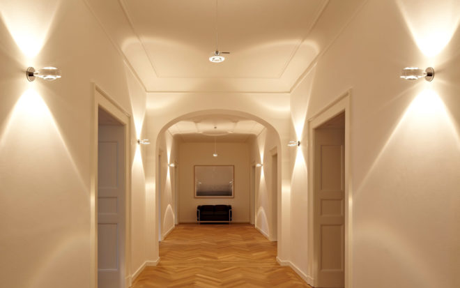
To save space in the corridors and living rooms, a two-button walk-through switch is used. The device increases the comfort of controlling light sources from several points. Before starting installation, it is worth designing the location of the wiring and focusing on the geometry of the room.
Features of a two-key switch
The two-gang switch is connected to the lighting circuit through the second changeover contact of each switch with two cables between them. In fact, the device is a dual single-key model with four wires. The electrical circuit of each core is an autonomous element of the lighting line that provides power to a specific lamp without interacting with the rest of the parts.
Depending on the brand, 2 to 4 terminals are present at the inputs and outputs of the device. For example, circuit breakers with a 1st phase terminal, 1 output terminal per bulb, 4 terminals for intermediate cables are available.
The convenience of two-key models is the ability to activate light from different angles of the room.
Design differences
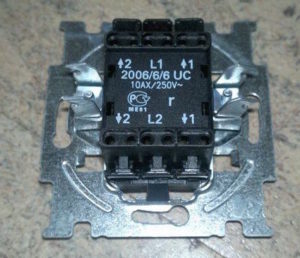
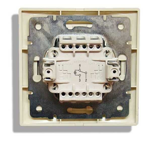
Structurally, the DPV is the stationary contacts of the housing and the movable spring rolling mechanism. A plastic or ceramic frame is designed for mounting terminal blocks and switching. The contacts of the device are 4-6, some brands number them.
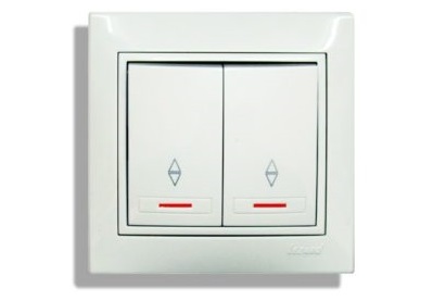
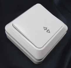
The toggle switch is made with two keys without standard designations, but its dual purpose can be judged by the multidirectional arrows. Buttons in a single case are distinguished by the independence of circuits, which provides control of two lighting lines. The electrical circuit is closed independently with 2 buttons.
How does 2-key PV work
The functionality of a double switch is similar to a single switch. The main difference is in the connection of two identical elements in one housing, which expands the capabilities of the device. When the switch button is pressed, the contacts are switched over, the circuit is closed and the lamp lights up. The exception, i.e. switching in the reverse order provides an open circuit.
The light-on algorithm is indicated by the arrows on the keys.
Scope of use
The installation of a double pass-through switch due to a switching capacity of 16 A is only allowed to control a line with a load of up to 3 kW. The device is used:
- to control the light in the bathroom and toilet from one element;
- adjusting the brightness of the lamp on the chandelier;
- on / off LED strip stretch ceiling;
- activation and shutdown of nightlights;
- creating lighting in a room with several lamps;
- group control of bulbs in the halls and corridors.
The use of double switches saves wires directed to single models.
Types of devices
Before connecting the DPV, you need to deal with the classification. Knowing the features of installation, type of activation will help you choose the right switch.
By installation method
There are two varieties:
- Internal, or "recessed." They are located in the wall as an element of hidden wiring. The cable is laid in the strobe or inside the GCR. To connect the switch, you will need to additionally put a socket for the working part in the hole.Mounting grooves are brought to it.
- Outdoor. They are installed in case of laying wires in a corrugation or duct over a wall. On porcelain insulators in boxes do not fit. Outdoor switches are justified in wooden dachas, outbuildings and utility rooms.
Use outdoor models for temporary wiring.
By the type of operation of the key spring
The two-key switch operates according to the following principles:
- Compression: when pressed on the button, the force is applied to the ball, which compresses the spring. The element slides along the axis of swing of the rocker arm, and moving along its shoulder, provides movement of the active node with contacts.
- Stretching: there is a frame on the key pressed against the base of the spring. The part swings along the axis, breaking or creating an electrical contact.
Regardless of the mechanism, the active part switches.
By the way of switching elements
DPV can be connected using screw or screwless clamps.
When installed on screw terminals, the main difficulty is the lack of contact marking. You will need an indicator screwdriver to search for an input. Phase sockets are located at the top of the ceramic body. Before connecting, 0.7 cm is removed from the wires.
The phase is brought to the upper contact by inserting the cleaned area into the gap formed when the screw is untwisted. The two remaining contacts are connected in the same way.
In screwless models, the contact of the conductors is carried out using conductive fittings. An insulating layer is removed from the wire 8-10 cm long. The phase core is thrown onto the input contact at the top of the panel. It is determined by marker 1 or L.
The stripped part of the wire is placed in a special opening. Fixation takes place using the internal spring assembly. The remaining cores without insulation coating are installed in the sockets for output contacts.
Screw clamps must be tightened periodically.
Wiring diagram
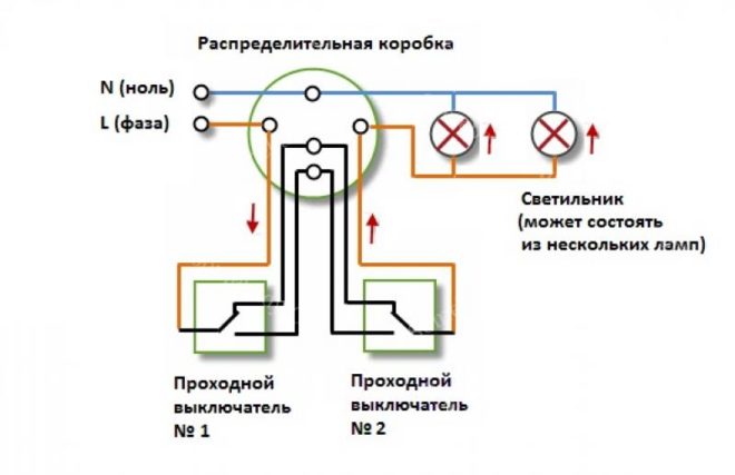
The standard wiring diagram for the two-key walk-through switch provides for the presence of:
- distribution box 10-30 cm below the ceiling line;
- the main device - DPV;
- fixtures in two rooms.
After installing the equipment, it must be connected into a single system as follows:
- Turn off the opening apartment machine.
- Find a two-wire cable with zero and phase in the distribution box.
- Lead the phase wire from the distribution box to the fixed contact of the input.
- Using two more phase wires, connect the fixed bypass contacts to the lamp holders.
- On one contact of the cartridge to throw a phase core, on the second - zero and connect it to zero power in the distribution box.
Connection of input contacts is only allowed by phase.
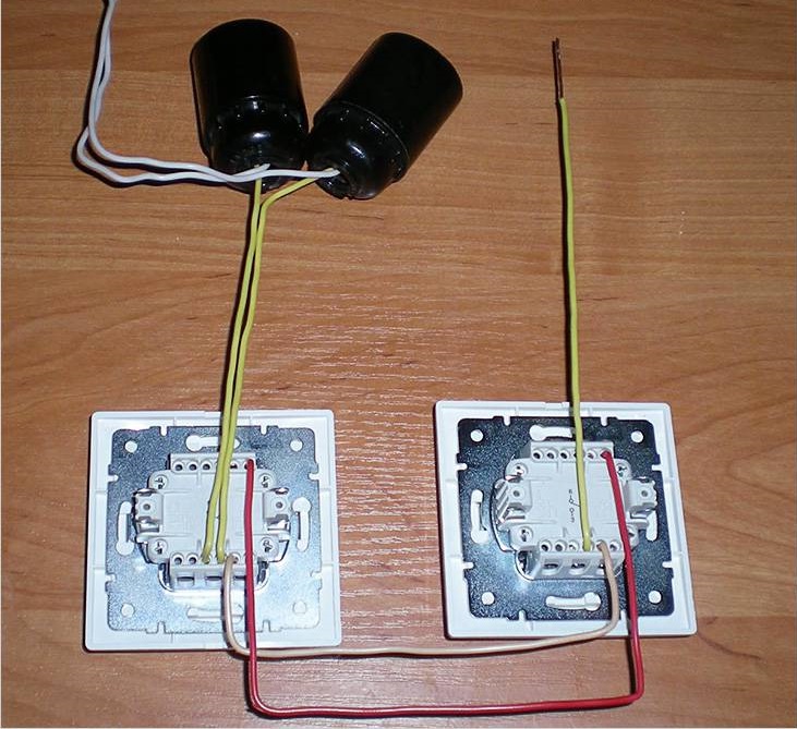
Connect two devices from two points
The scheme provides for the arrangement of two groups of bulbs at the beginning and at the end of the room for ease of management. In order to save cable, a junction box is placed next to the shield.
Procedure and General Requirements
A step-by-step installation algorithm provides for the selection of wires with the calculation of the cross-section and length, the connection of wires, the wiring of the structure.
After selecting the cable:
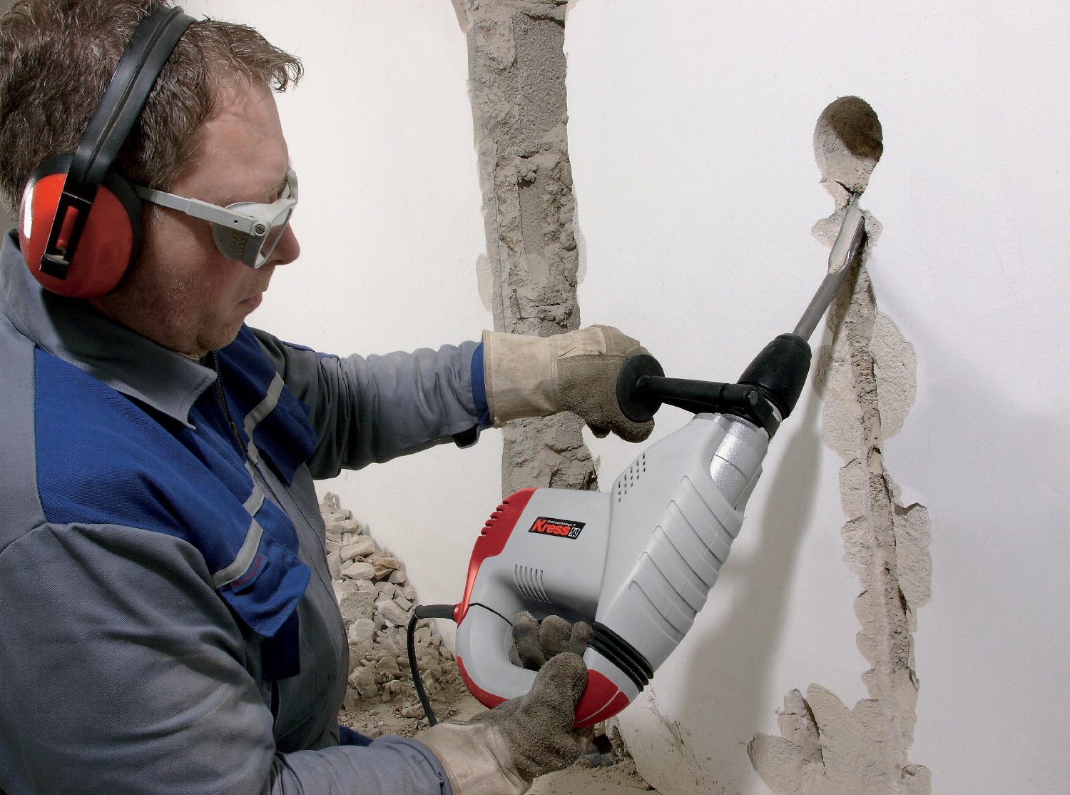
- Puncher drills holes in a brick or concrete surface. They work with a crown, departing from the ceiling 15-20 cm.
- In the vertical direction, at a distance of 60-90 cm from the floor surface, a niche is drilled for the 1st socket.
- On the opposite side, a strob is made under the second sub-rosette.
- A cable with a large cross-section is laid from the switchboard to the distribution box.
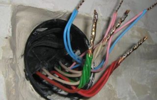 Connection of wires in the distribution box by soldering
 - From the box to the switches, a line of 2 wires with 3 wires is organized. Their cross section should be smaller.
- Three-core cables laid according to the scheme are used for the line of lighting devices.
- Loops of 30-40 cm are executed under the shades.
- The cable ends are laid in the junction box and in the sub-rosets.
- Cases are placed in niches, mounted on a gypsum mixture.

After the gypsum hardens, the insulation layer is removed from the ends, the wire is connected, the lamps and sockets are connected.
Tools and materials
For installation, you will need to purchase a distribution box, 2 internal sockets for a concrete and brick wall, 2 DPV devices, lighting elements. Installation of switching devices is carried out using pliers, level, wrenches, nippers, stationery knife, screwdriver, terminal blocks, electrical tape.
Section of a power cable by group power consumption
Installation of a dual switch is carried out using a wire with 6 cores. It is allowed to use a different type of labeling - VVG, PUNP, GDP, MYN, but only with double insulation and copper conductors. The section of products is selected in accordance with the table.
| power, kWt | Current, A | Length m | Section mm2 |
| 1 | 4,6 | 34,5 | 1 |
| 2 | 9 | 17,5 | 1 |
| 3 | 13,5 | 17,5 | 1,5 |
| 3,5 | 16 | 24,5 | 2,5 |
| 4 | 18 | 21,5 | 2,5 |
| 6 | 27 | 23 | 4 |
| 8 | 36,5 | 25 | 6 |
The mismatch of the length, total power and cross-section of the wire will lead to overheating of the contacts and damage to the network.
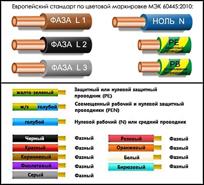 The color of the wires is taken on the basis of SNiP, GOST R-50462-92 and Ch. 1 PUE:
- neutral - blue or blue;
- grounding is yellow-green;
- phase and points of its switching - black, red.
Sometimes it is allowed to use the white phase.
Connection of a two-gang switch through passage for control from 2 places
It is advisable to implement a wiring diagram for a two-key passage switch for 2 points before work on the interior decoration of the room. It is performed step by step:
- Strobing - one from the air supply to the distribution box, two in the opposite direction, one from the distribution box to the lighting fixtures.
- Selection of conductors for the section from the distribution box to the first switch. 2 cables with 3 wires or 3 cables with 2 wires are suitable.
- Lead two wires to supply voltage to the first switch, and the remaining four to the second through the junction box.
- Connection on the second DPV in the strobe of 3 two-wire cables. Two wires should be directed to the light sources, the remaining 4 - to the first switching device.
- Connection to the lighting device 1-2 neutral conductors.
- Laying a two-core power cable to the distribution box.
Choose the size of the box so that it fits 16 wires at least.
Features desoldering two-key PV
When executing the two-pass switch circuit breaker, you need to think about a way to fix the wires. Popular technologies include twisting followed by soldering or welding of the ends.
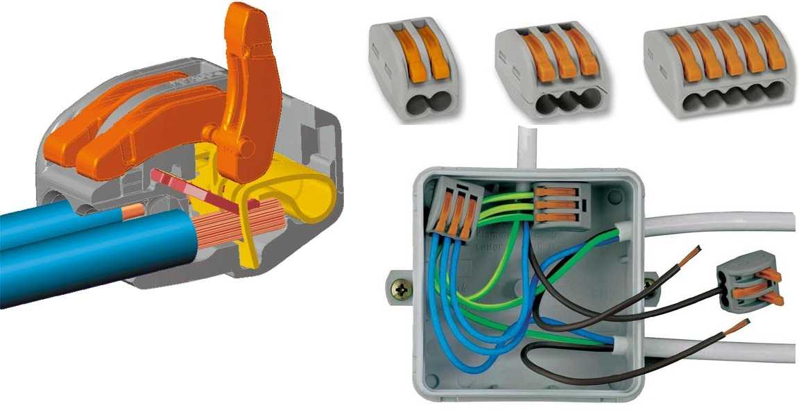
A popular mounting method is to mount wiring elements with spring clips on the contacts. For the strength of the electrical connection and quick assembly, it is advisable to use:
- WAGO Terminals. Reusable clamping clips that are removed during line repair.
- Werkel clamps. Located at the ends of the contacts. By pressing a button on the terminal, a hole opens. The end of the wire is inserted into it without insulation.
The phase end pops into the first contact. A jumper is made between him and the first.
The main mistakes when setting the switches
In the process of connecting two-key models of switches, beginners make several mistakes:
- Small wire length. 15-20 cm should remain in the distribution box for twisting.
- Insulation remains on the cable. From the top, the coating is removed almost completely, from the veins - by 3-5 cm. This is necessary for the convenience of implementing the scheme and high-quality twisting.
- The bulbs are connected in series. Parallel connection ensures the normal operation of the line when one element burns out.
- On the DPV, they start the neutral.It is necessary to take a phase to prevent line closure, leading to breakdowns of household appliances.
- The switchgear and the socket boxes are put on gypsum without cable ends winding. Touching exposed wires is not safe.
Podrozetniki should be masked with decorative panels.
Two-key switch models are stand-alone devices in a single enclosure. The convenience of their operation is to control the light from different areas of the room. For proper installation, you will need to select the wire cross section and purchase it with a margin of length.