The installation of an electric energy meter in the house will help to keep an accurate record of the resources spent on the farm and save finances by paying for electricity not at the default rate, but at real costs. To ensure the safety and reliable operation of the device, the correct connection diagram of the Mercury 201 counter must be selected.
Basic requirements for meters Mercury 201
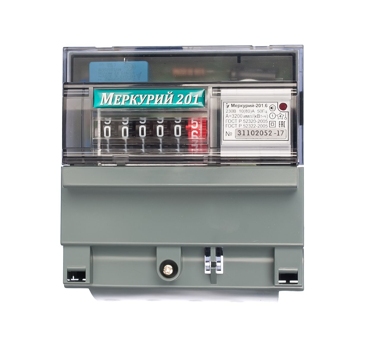
When purchasing a meter, you need to take into account that no more than a year passes in the case of devices with two phases and a maximum of 2 years if a single-phase device is selected, from the day it was released (it is taken as the date of initial calibration). There should be a seal on the device with an exit date stamped on it - its presence is necessary for warranty service.
A holographic sticker confirming the authenticity of the product and the stamp of a state inspector, indicating that the product meets the specified accuracy category, must also be present on the meter case.
Electric meter replacement
In order to replace the old apparatus with “Mercury”, the consumer of power supply services should send a request to the HOA department of his city about the requirements for meters (including regarding accuracy class). Having received this data, he buys a suitable device.
Before dismantling the old meter, you must once again contact the authority, having agreed to meet with the inspector, whose task will attest to the integrity of the seal. If the consumer removes the meter without this procedure, they can be attributed to the theft of electricity and a fine.
The inspector will look at the seal, draw up an act on the dismantling of the old device and set a tariff for the consumer based on data on electricity consumption over the past few months.
Before you install and connect the meter, you will need to de-energize the power line, if the switch is behind the device, or turn off the input circuit breaker.
Connect Mercury 201
There are 2 ways to connect the Mercury 201 counter, differing in its position relative to the machine, from which electricity enters the network. Electrical installation rules prescribe that the meter must be connected after the machine. However, energy distribution companies allow its use only if it is possible to seal an automatic device. If this procedure cannot be carried out, the meter is connected in front of the machine. Then an input wire will be connected to the device. To do this, you need to contact the HOA with a request to turn off the current on the line.
The sequence of actions for direct connection of the device:
- take it out of the box and unscrew the screws holding the terminal block panel;
- strip insulation material at the ends of the connected wires by 1 cm;
- connect them to the desired clamps and tighten the screws;
- plugs are removed in the panel - there will be holes for wiring in their place;
- put the panel in place;
- the inspector makes a seal;
- power is supplied to the line - if the operations are performed correctly, the scarlet diode will burn on the device in front.
Products with three phases - Mercury 230 - are placed in the same way if the total load power is not more than 60 kW. If it exceeds this indicator, use a modification of the circuit, including a step-down transformer.
Wiring diagram
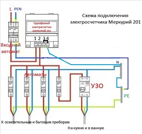 You can find the connection diagram with other network elements in the device’s operating instructions or use the information found on the Internet. Two types of instrument connection are practiced - direct and using a current transformer. The first option is used to connect any of the two types of devices (both single and three phase), the second for a device with three phases with a load of 60 kW and above.
In the case of using a direct connection circuit of the Mercury 201 electric meter, the device is connected directly to the transmission main line. The semi-indirect circuit with transformers suggests that the house has a large number of electrical appliances that create a very high voltage in the network. The current-transformer device used in this circuit uses a phase wire as the primary winding. A number of additional requirements are imposed on the installation of meters according to this scheme. Appropriate regulation can be obtained by contacting the HOA.
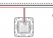
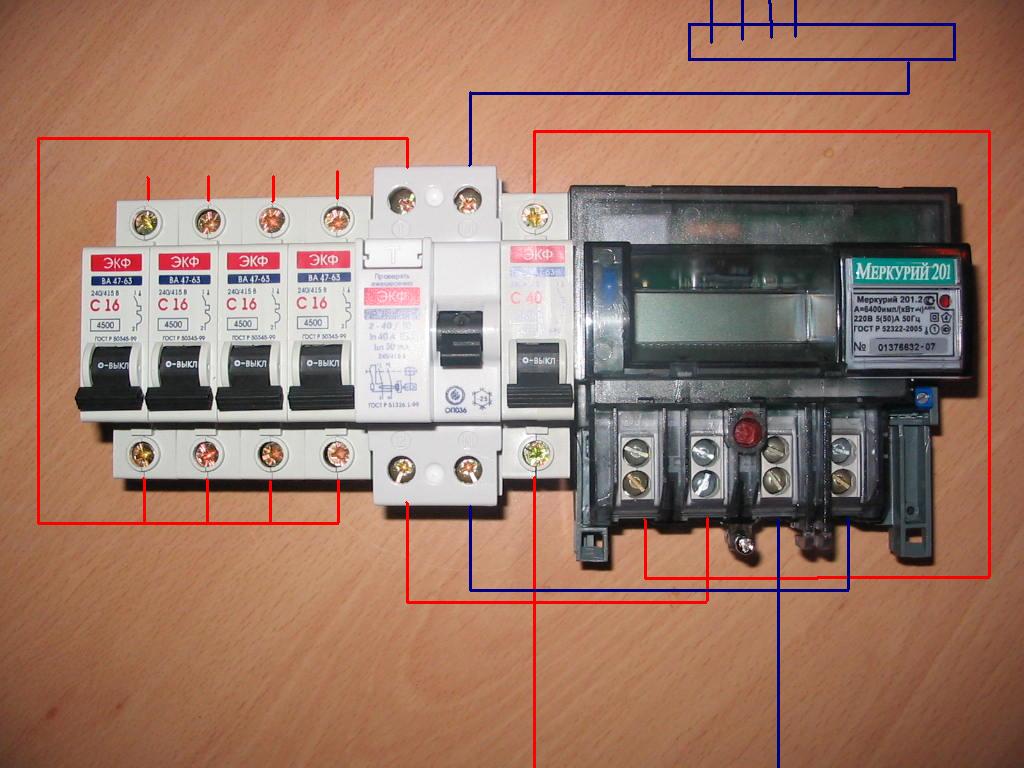
Four-terminal wiring diagram with circuit breakers
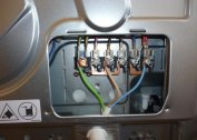
Here the points are interconnected in the following order (from left to right): first, the phase wiring is connected from the external network, then the phase is connected to the load going to the apartment or private building. After that, neutrals are connected in a similar way - first from the external network, then to the load cable.
Four checks by E.M. 201 correct readings
After installing the meter, it is necessary to verify the correctness of its connection and operation by conducting a series of test measures aimed at fixing significant indicators of its functioning.
The first check is that the connection is correct
At this stage, the reconciliation is made with the scheme that the user was guided by when installing the product. The devices of the Mercury series are able to work correctly when changing places of zero and phase, but the rules of electrical safety require strict adherence to the installation sequence presented in the typical scheme.
The second check is for self-propelled
To carry out this verification phase, you will need to first create a situation of complete lack of electricity consumption in the apartment. To do this, it is necessary to cut down all automatic switches located below the electric meter and supplying lighting devices and sockets. If there are no separate switches in the network, the cords of all household electrical appliances and extension cords are pulled out of the sockets, and the light switches are put into inactive mode.
A quarter of an hour after turning off all the devices, it is necessary to evaluate the functioning of the electric meter - if it works properly, the roller on the counting mechanism should stop, and the lamp on the front of the device should not blink. Allowed maximum is a single blink or counter revolution every 5-10 minutes.
If the rotation of the roller or blinking takes place, the check is considered failed. Then a laboratory test of the functionality of the counter is required.
The third check - measurement error
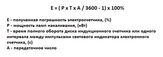
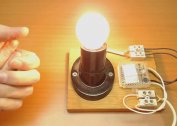
Here, the metering error of the electricity meter is calculated. You will need to prepare a mobile phone with a stopwatch and calculator (or the devices themselves), an electronic multimeter and an incandescent lamp in the role of a load device. It is not recommended to use household appliances, since the practical values during the operation of the devices may differ from those indicated in the passports, creating additional errors, sometimes significant.
Procedure for verification:
- Measure the voltage at the outlet with a multimeter.
- They put the device in the mode of measuring the current strength, connect it to the lamp, measure the value of the indicator.
- The real power and resistance of the lamp are calculated - for the first case, you need to multiply the two indicators obtained above, for the second - divide the voltage by the current strength.
- Continuing to keep the lamp plugged in, they calculate the time during which the roller will make 10 revolutions (at a stable voltage), and record this time in seconds.
- The instrument constant indicated on the front of the housing is recorded for calculations.
- Find the actual electricity consumption: squared power and then divided by resistance.
- Multiply the figure from the previous calculation by the number of seconds and divide by 3600 (the number of seconds per hour) - the unit of measurement of the resulting value will be W-hour.
- 1000 is multiplied by the number of revolutions (in this case 10) and divided by the counter constant.
Now the actual error is considered. From the number obtained in the penultimate paragraph, subtract the one found in the last, divide this number by the last digit and multiply by 100. The result is expressed as a percentage (for example, -5%). A deviation of up to 10% in one direction or another is considered acceptable.
The fourth test is for magnetization.
This check is very simple: a thin sewing needle is brought to the front of the device. If it is attracted, it indicates magnetization. If a few days after the magnet is removed, it does not resolve itself, you will need to purchase a demagnetizing device.
When installing Mercury meters operating on one or three phases, the correct connection is crucial in accordance with the established scheme. After that, you will need to check the functioning, independence of the device and measure the error obtained during operation of the electric meter.