Historically, it is more profitable and cheaper to get electricity in the form of alternating current generated by power station generators. Such a representation made it possible to efficiently transmit it over vast distances. At the receiving end, it was converted into a single-phase voltage, convenient for consumers, and in this form entered the power line. However, the internal circuits of most modern power receivers need constant power supply, the value of which is selected from a standard series of values of 5, 9, 12, 24, 36 or 48 Volts. To obtain them, a special voltage rectifier (for 24 Volts, for example) had to be introduced into the circuit of electronic devices.
The principle of operation of the rectifier
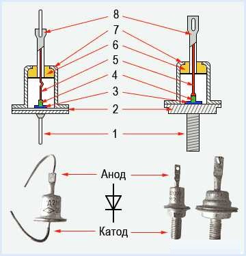
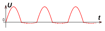
For a clear understanding of the principle of operation of a DC rectifier, you will first have to consider that semiconductor elements (diodes) are used to rectify an alternating voltage. Their distinguishing feature is the ability to conduct current in only one direction. Due to this property, the alternating voltage applied to them at the output will take the form of positive ripples with the lower halves of the half-oscillation period cut off. With positive half-waves, a current will flow through the diode, which is the basis for the formation of a constant power supply. To obtain it, additional electrical elements are needed.
Any current rectifier incorporates the following main nodes:
- A step-down transformer that converts 220 volts to the desired value;
- a set of diodes (bridge);
- smoothing (filtering) capacitor;
- stabilizer made on the basis of transistor elements.
There are many options for electronic rectifiers, differing in the number and method of connecting the diodes, as well as their operating parameters. Of particular interest are the various approaches to the inclusion of diode elements in the circuit. The stabilizing cascade of the rectifier device is assembled on transistor switches, called electronic relays.
Types of rectifiers

Depending on the method of switching on semiconductor diodes, all AC rectifiers are divided into the following types:
- half-wave (half-wave);
- two-half-wave (full-wave with a midpoint or Mitkevich scheme);
- Gretz bridge or rectifiers;
- rectifiers with doubling of the operating voltage and other, less common circuits.
Half-wave switching is the simplest method used to rectify alternating current. Another name is zero rectifier circuit.
Using devices of this class, it is possible to obtain only a pulsating (used only half) output current. Schemes based on the half-wave principle are characterized by low conversion efficiency and are rarely used. Their half-wave counterparts include two diodes and provide half-wave rectification of both polarities. They are more efficient and are used in simple power supplies.
Single-phase bridge rectifiers, the so-called Gretz circuits with 4 diodes, are characterized by high efficiency, which is understood as the efficiency of using the power received from the transformer.
The voltage at the output of the semiconductor rectifier bridges is a good basis for subsequent smoothing and stabilization - to obtain direct current.
They are widely used in devices of increased energy intensity such as generators with output voltages from tens to hundreds of volts. Their advantages include:
- low reverse voltage (Volta fractions);
- small dimensions;
- high efficiency of using a transformer (in comparison with the Mitkevich scheme).
A significant drawback of bridge circuits is the double voltage drop across the diodes, which forces them to select the output parameters of the transformer with a margin during their development. This part of the useful power is then lost at the junctions of the four diodes.
Types of Rectifiers by Functionality
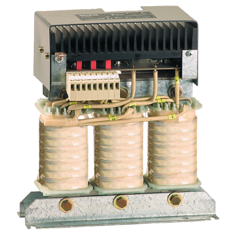
According to their purpose and functionality, known rectifier samples are divided into single-phase and three-phase devices. The former are used in the electric networks of apartment buildings and private houses and are intended for powering household appliances. The second ones are an electronic module of 3 units of the same type, manufactured according to one of the following schemes:
- single-cycle rectifiers;
- push-pull systems;
- combined modules: with two three-phase windings with parallel and series connection of diodes.
The use of single-cycle transformation schemes is limited due to the low efficiency of the rectified voltage. Their push-pull analogues are widely used in DC motors and other electrical machines containing brush assemblies in their design. In addition to the classic rectifiers designed for installation in commutator motors, there are schemes that can increase the output voltage several times. A special case of such solutions is a voltage doubling rectifier.
The rectifier circuit with voltage doubling only differs in details from the options already considered. Such devices are commonly called multipliers, which are easily assembled with their own hands.
Basic relationships when calculating the rectifier
 To calculate a 2-half-wave rectifier selected as an example, you need to know the following initial data:
- input voltage acting in the secondary winding of the transformer;
- current in diodes flowing in the circuit taking into account the load;
- capacitance of an electrolytic capacitor, selected based on a given ripple smoothing coefficient;
- maximum voltage on it.
It is important to consider the voltage drop across solid state diodes in the open state.
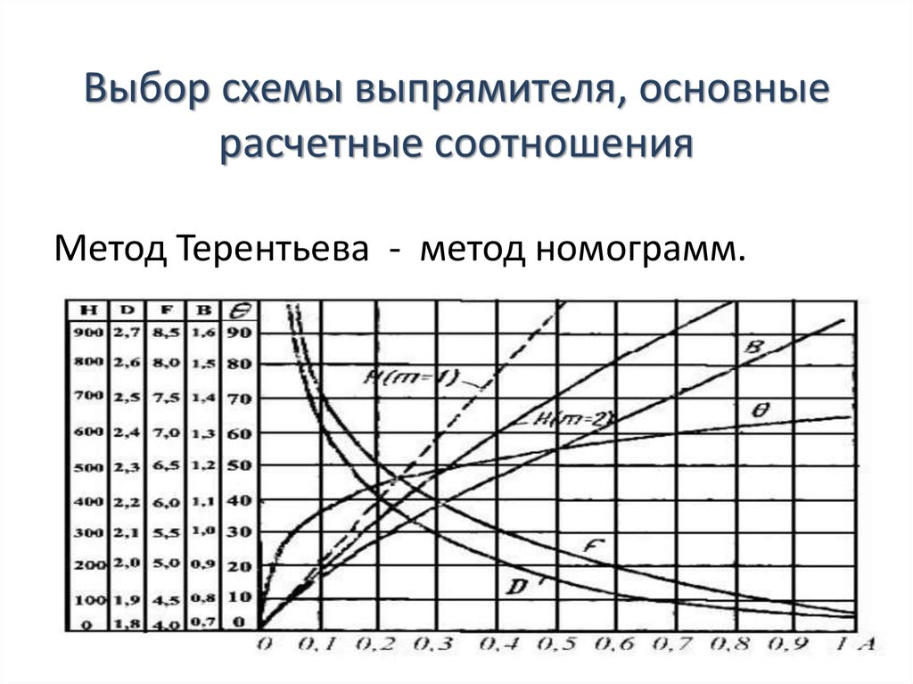
The calculated ratios for this case are presented in the following form.
- The current in the transformer winding is equal in magnitude to its maximum value in the load (Iobm = Inagr).
- The voltage in the secondary winding in idle mode is U2≈ 0.75Uload.
- Rectifier diodes are recommended with the following parameters: Ureb> 3.14Unag, and Imax> 1.57Inag.
Rectifiers are widely used in various fields of electrical engineering and electronics, including modern control systems. Therefore, it is so important to understand what current rectifiers are and what their varieties are used to build the most efficient circuits.