The total load current on the line of a residential, commercial facility or enterprise in some cases may exceed its actual capabilities. The correct design of the current transformer will help ensure the quality of the linear conversion, control and protection of the mains.
Reasons for installing current transformers
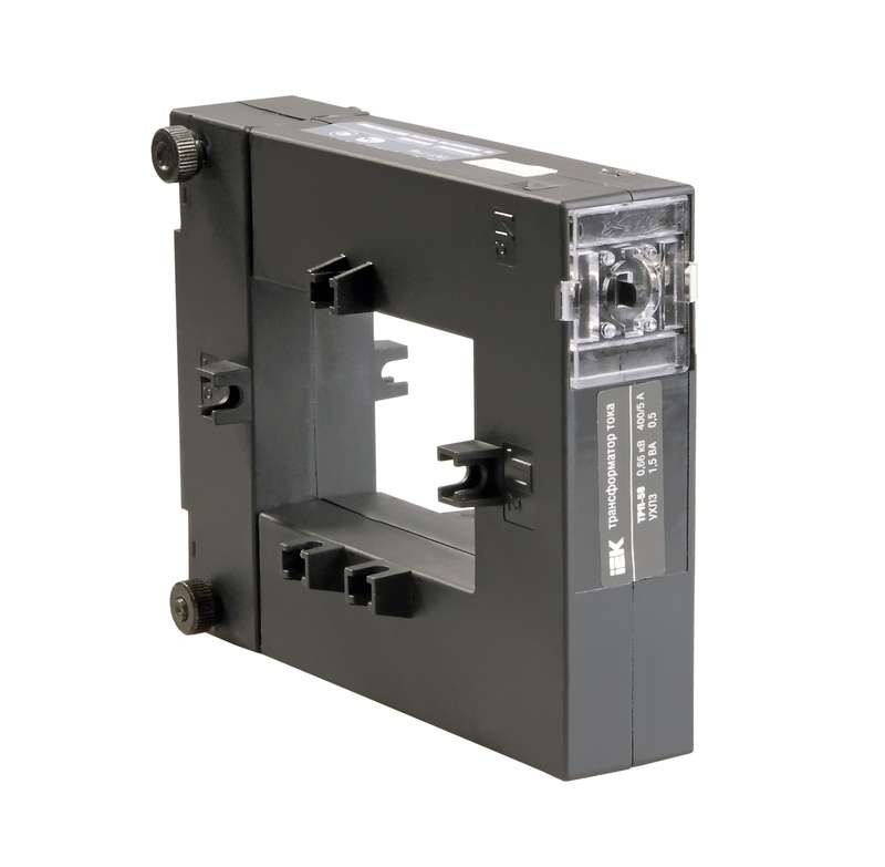
The device is designed to transform the primary current value to safe for the network. Transformers are also used to:
- the distinction of low-voltage accounting equipment and relays, thrown to the secondary winding, if the network is primary high voltage;
- increase or decrease voltage indicators;
- measuring the state of the mains and the parameters of the alternating current;
- safety of repair and diagnostic work;
- fast activation of relay protection during short circuits;
- metering of energy costs - an electric meter is usually combined with them.
For measurement, you will need to connect the CT to the wire break, and connect a voltmeter or ammeter combined with a resistor to the secondary mark.
Varieties of current transformers
 Choosing a device that is suitable for mains voltage or specific work is necessary on the basis of classification according to various criteria.
Appointment
There are such transformers:
- measuring - measure the circuit parameters;
- protective - prevent overloads, equipment failure;
- intermediate - are connected to the circuit with relay protection, equalize currents in differential protection circuits;
- laboratory - are highly accurate.
Laboratory models have more conversion factors.
Mounting type
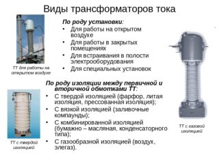
For a private house and apartment, you can choose an apparatus mounted inside or outside the room. Some modifications are built into the equipment, as well as worn on the passage insulation. For measurement and laboratory tests, portable models are used.
Primary winding design
There are bus, single-turn (with a rod) and multi-turn (with a coil, loop type winding and "eight") devices.
Type of insulation
The following converters are:
- dry insulation - based on cast epoxy, porcelain or bakelite;
- oil-paper - standard or capacitor;
- gas-filled - inside is inorganic gas with high breakdown voltage;
- compound - inside is filled with thermoactive and thermoplastic resin.
The compound has the highest moisture resistance.
Depending on the number of stages of transformation, one-stage and cascade models can be selected. The entire line has an operating voltage of more than 1000 V.
Accuracy class
The accuracy class of the current transformer is prescribed in GOST 7746-2001 and depends on its purpose, as well as the parameters of the primary current and secondary load:
- Under conditions of low resistance, almost complete shunting of the magnetized branch occurs. The device works with a large error.
- With increasing resistance, the error also increases. The reason is the functioning of the device at the saturation site.
- With a minimum primary current rating, the transformer operates in the lower part of the magnetized curve, with a maximum value in the saturation region.
Exact selection of the transformer according to the accuracy class can be made based on the table.
| Accuracy class | Primary current rating in% | Secondary load limit in% |
| 0,1 | 5, 20, 100-200 | 25-100 |
| 0,2 | ||
| 0.2 s | 1,5, 20, 100, 120 | |
| 0,5 | 5, 20, 100, 120 | |
| 0.5 s | 1, 5, 20, 100, 120 | |
| 1 | 5, 20, 100-120 | |
| 3 | 50-120 | 50-100 |
| 5 | ||
| 10 |
For protection devices, the accuracy class is also determined from the table.
| Accuracy class | Marginal error | Secondary Load Limit Percentage | ||
| thermal | angular | |||
| min | wed | |||
| 5P | ±1 | ±60 | ±1,8 | 5 |
| 10P | ±3 | There is no norm | 10 | |
For energy metering, models with an accuracy class of 0.2S - 0.5 are used, for ammeters with a minimum sensitivity - from 1 or 3, for relay protection - 5P and 10P.
Features of choice
 In the process of choosing a current transformer, you must be guided by the basic parameters:
- Mains voltage rating. The rated value must be greater than or equal to the operating voltage.
- Primary and secondary winding current. The first indicator depends on the transformation ratio, the second depends on which counter.
- Conversion factor. It is selected according to the load in emergency cases, but PUEs establish the need to install devices with a coefficient greater than the nominal one.
- Accuracy class. Depends on the intended use of the counter. At a commercial enterprise, 0.5S devices are justified, in a private house - 1S.
The design is determined by the type of meter. For models up to 18 kV, a single-phase or three-phase device is suitable. If the value is greater than 18 kV, a single-phase transformer is used.
Selection of a current transformer for the organization of relay protection
The relay current transformer is characterized by accuracy class 10P and 5P. In the PUE it is established that its error should not be more than 10% in current and 7 degrees in angle. If the error is exceeded, additional equipment is installed.
Under normal conditions, a transformer relay determines the type of failure (low voltage, over / under current or frequency). After measuring the parameters and detecting deviations, protection is activated - the network is de-energized.
The nuances of choosing devices for the accounting chain
To the metering circuit for the correctness of measurements, devices with an accuracy class of not more than 0.5 (S) can be connected. In the presence of oscillations and accidents, the graphs of the flow of current and voltage are incorrect. Failure to comply with the accuracy class may lead to an overestimation of the meter.
In clause 1.5.17 of the PUE it is established that with an overestimated coefficient, the transformer for the metering circuit must have a secondary current:
- at maximum load - not more than 40%;
- at minimum load - not more than 5%;
- accuracy class - from 25 to 100% of the nominal.
The power factor CT is from 1 to 5% of the primary.
Table of preliminary selection of current transformer by power and current
It is advisable to make a table selection of equipment after clarifying the technical parameters of the apparatus. If they are known, it is worth choosing a CT according to the table, where power, load and transformation coefficient are indicated.
| Maximum power in the calculation, kVA | 380 V network | |
| Load, A | Transformation coefficient, A | |
| 10 | 16 | 20/5 |
| 15 | 23 | 30/5 |
| 20 | 30 | 30/5 |
| 25 | 38 | 40/5 |
| 35 | 53 | 50/5 or 75/5 |
| 40 | 61 | 75/5 |
| 50 | 77 | 75/5 or 100/5 |
For a network with a voltage of 1.5 kV, a similar table is used.
| Maximum power in the calculation, kVA | 1.5 kV network | |
| Load, A | Transformation coefficient, A | |
| 100 | 6 | 10/5 |
| 160 | 9 | 10/5 |
| 180 | 10 | 10/5 or 15/5 |
| 240 | 13 | 15/5 |
When using the tabular method, it must be taken into account that the secondary current of the device should not be more than 110% of the nominal value.
Reliability of voltage measuring transformers in an isolated neutral network
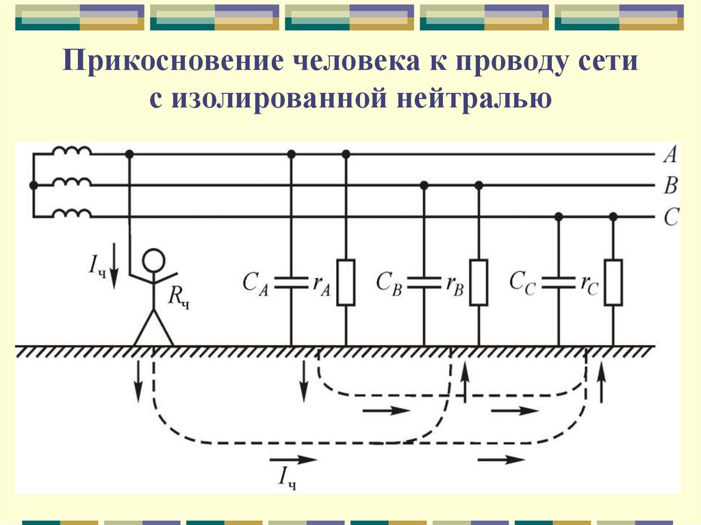 A simple measuring device is designed to lower the voltage ratings that are supplied to the meters and protective relays connected to the 6-10 kV network. The transformer only works properly under neutral ground conditions.
In ferroresonant reactions (interruption of the power transmission line phase, touch by branches, dripping of dew drops on wires, incorrect switching), there are risks of voltage transformer breakdowns. The failure rate is 17 and 25 Hz. Under these conditions, overcurrent flows through the primary winding and it burns out.
If the Star-Star scheme is used, in the conditions of increasing voltage, the induction of the magnetic circuit increases. The device burns out. This process can be prevented by:
- decrease in indicators of working induction;
- network connection of devices damping resistance;
- creating a three-phase device with a common magnetic five-rod system;
- operation of devices connected to the network when opening a triangle;
- neutral grounding through a current-limiting reactor.
The simplest option is to use special windings or relay circuits.
Calculation of current transformer by power
 A current transformer is placed on 3 wires, but models with an accuracy class of 0.5S, where one ring goes to one phase, can be connected to a single-core cable. Before installing the device, it is calculated.
10 kV calculation example
10 kV models are suitable for commercial energy metering. For calculations, you can use the online program - a calculator. After entering data in the fields and pressing the calculation button, the necessary information appears.
If there is no program, you can calculate the device parameters yourself. It will be necessary to convert the three-second current of thermal resistance to one-second. To do this, use the formula I3s = I1s / 1.732.
The complexity of using this device is the minimum, about 10 A, power circuit current.
Current transformers installed at the factory or in an apartment building are not calculated on their own. You will need to contact the energy supply company to obtain the technical specifications with the model of the metering unit and the type of device, the rating of the machines. This eliminates the complexity of self-calculations.
https: //