In order to troubleshoot household appliances, an electric cable is required to ring the wires with a multimeter. Using a tester allows you to clarify open circuits, the presence of a short circuit, the resistance of the power line. To ensure the safety of work, you need to understand the features of the application of the device.
The need for wire continuity
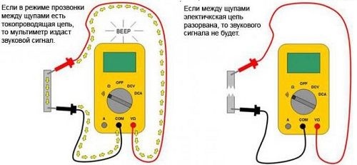
The dialing process involves the appearance of a buzzer if there is an electrical connection on the test sites. Verification is performed in the following cases:
- The switch or outlet does not work. Initially, you need to inspect the connections in the distribution box, check the lamp. Then the wire rings - the multimeter will give a signal about the problem.
- The network is overloaded. The use of a powerful punch for drilling walls can cause a break in telecommunications.
- Short circuit. Most often observed when the line is overloaded or as a result of wiring obsolescence.
- The search lived in large areas of the highway. The device is used in cases of impossibility to determine the conductor by color marking.
- Damage to household appliances. The dial is determined by the performance of switches, lamps, irons.
- Repair and soldering circuit boards. Testing the circuit with a multimeter is a mandatory stage of work.
All devices with a LED marker have a dialing mode.
Wire tester multimeter

The tester allows you to determine the presence of voltage, resistance and current parameters. It consists of a display, a selection knob, ports, probes / probes, and a power source. Depending on the type of counter, there are modifications:
- Digital DTM devices with a digital screen to display the measurement.
- Analogue AMM devices with current converters and a magnetoelectric ammeter measure the parameters of Hi-Fi equipment.
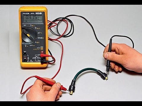
- Fluke It is equipped with two probes - positive (black) and negative (red), a 9 V power supply, and an electronic display. Internal nodes are represented by a signal conditioning circuit and an analog-to-digital converter.
Some modifications measure the capacitance of capacitors, check transistors and diodes.
Markings on the front panel of the tester
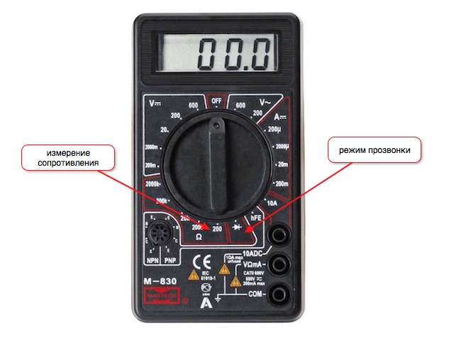
The prefix “multi” in the name means the ability to check several parameters. Their symbols are applied to the body in the form of physical signs or graphic drawings. On the front panel there are:
- U - voltage designation;
- In - voltage in volts;
- I - current, the strength of which is regulated by setting the handle on the icon;
- A - amperage;
- Ω, R - resistance marking;
- Ohm - resistance parameters in Ohms;
- - | | - - marking capacitors.
Graphic symbols are used for diodes and transistors.
A black probe is located in the device’s socket labeled COM. This is a common nest. The device can have 2-3 working holes for measuring voltage, low and high currents.
The hole marked U, Ω, Hz allows you to measure voltage, resistance, frequency, and test radio elements. This is where the dipstick is placed with which you can ring the cable or wires for a break.
The socket with the designation mA (mA) is designed to determine small (up to 1 A) and large (from 10 A) current.Next to them are symbols ~ or -, giving the concept of a constant or variable nature of the current or voltage.
Measured Range
In addition to marking the value of indicators on the front panel of the multimeter with manual adjustment, there are measurement limits. All values have the form of numbers that are multiples of the number "2". In the selection process, you need to put the value of the same order as the measured, but above it.
For example, to check the voltage of the outlet, you need to set the range of 2000 volts. The wire is drawn in resistance mode with a minimum value of 2 ohms. For long wires, 20 ohms is set.
Use the buzzer button while testing the circuit for a short circuit.
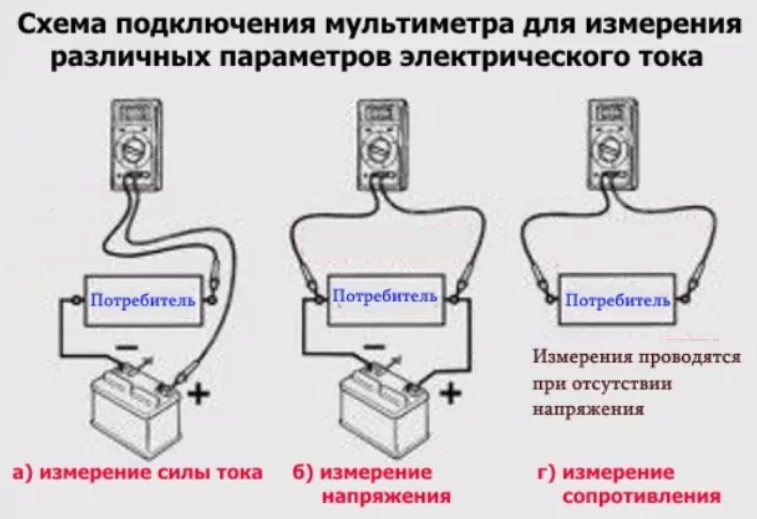
How to connect a tester
To check the parameters of the power line and ring the conductors with a multimeter, it must be included in the circuit. The testing area is located between the terminals of the device, i.e. it connects to the output of the circuit. When measuring voltage, the device is connected parallel to the test zone.
To measure the current parameters, the device pops up sequentially on an open circuit. A suitable place would be the point between the power supply output and the load terminal.
Features of continuity and resistance tests
 The dialing process is a complex of establishing the resistance of conductors, analyzing the result and outputting data to the screen with an audio signal. Resistance measurements are based on Ohm's law. It says that the current flowing over a certain section of the circuit is directly proportional to the voltage and inversely proportional to the resistance of this section. Ohm's law reflects the formula:
I = U / RwhereI - current strength U - voltage and R - resistance.
The tester works on this principle. Having two parameters, it is easy to calculate the third. The power source of the multimeter generates voltage and supplies current. Resistance measurements are displayed:
- zeros - the actual value is less than used;
- digits with the first digit of zero - the indicator is less by 1 division;
- digits more than 1 - measurements are accurate.
After comparing the source data with the magnitude of the loss of the measurement object, you can calculate the final result.
Resistance Labeling on Digital Models - Ω.
Instrument Setup Procedure Before Testing
To check the wire for an open with a multimeter, you will need:
- Set the switch to dialing mode “-> »-” and activate the buzzer.
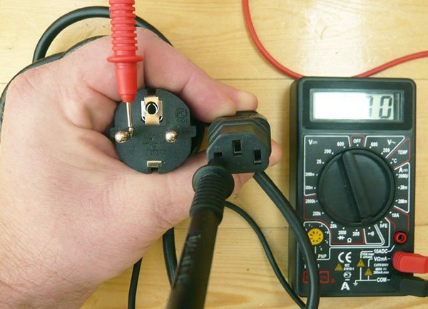
- Place the ends of the probes with probes in the sockets. Red is located in the VΩmA hole, black is in the COM. This is necessary to observe the polarity of the measurements.
- Test the device itself for a malfunction by closing the red and black probes with each other. A beep will be heard, and 0 or a value close to it will appear on the display.
If the wiring integrity is checked, polarity is not required.
Observance of safety measures and rules of work with a multimeter
It is necessary to ring the electric wires and work with the multimeter, following the safety rules:
- Testing elements disconnected from the circuit to prevent their influence on the circuit.
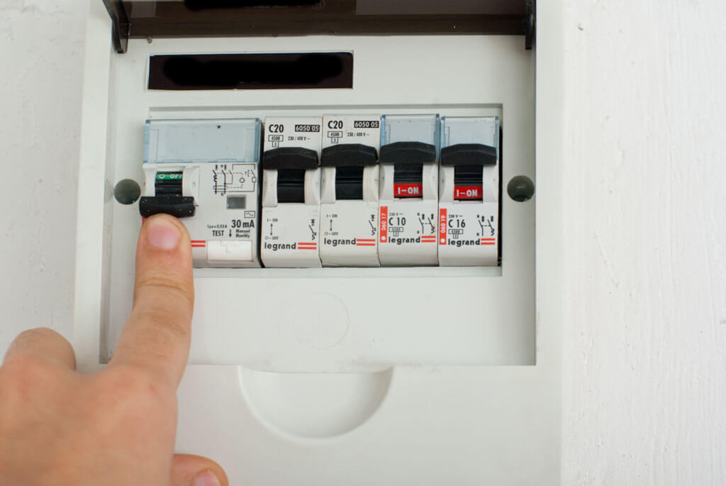
- Disconnect the circuit by disconnecting the power supply in the switchgear.
- Discharge capacitors by shorting them to prevent data distortion.
- Take into account the distortion of the results from the network diodes.
- Current leaks when you touch the wires and the tip of the probe with your hands will lead to incorrect results.
- Use crocodile tips at the ends of the meters for reliable contacts.
The distortion effect is noticeable when testing a large resistance.
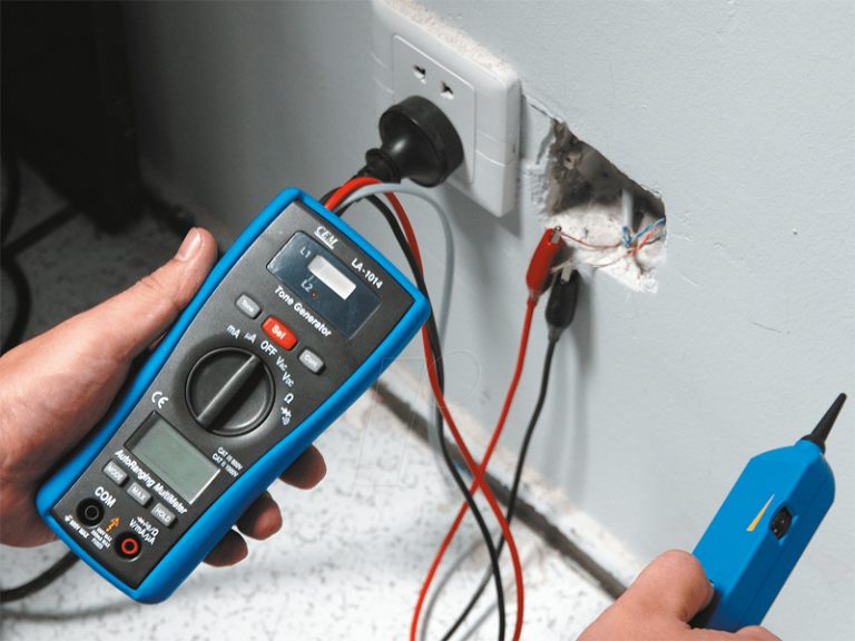
Wiring example
A concrete example of working with a tester would be a standard power grid. The apartment is connected to it according to the regulations, consumers are grouped, each line is powered through an individual automatic switchboard.
Situation: the outlet does not work in one room. The user's task will be to find the cause of the failure. To solve it, you will need:
- See if the automation has worked in the shield. If elements are included, de-energize a specific line or apartment completely.
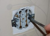
- Remove the socket from the socket, visually inspect for external defects and contact quality.
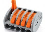
- For modern models, ring terminal blocks.
- If the outlet does not break, test the quality of the connection of the conductors in the junction box next to the outlet.
- The main cable in the switchgear should be torn, connected to the cores for the outlet and diverted to the next consumer.
- There are 3 twists in the distribution box - neutral, earth and phase. With the tip of the probe, you need to touch the bare twist.
- The second tip in turn contacts the socket contacts. You can fix one probe on the contact, and second check the twist.
There are no terminal blocks for standard outlets.
Features of the dialing process
Measurements have several nuances:
- If the twist is defect-free, it makes sense to test live wiring. It is necessary to apply current by turning on the shield machines.
- If there is doubt in the color coding, the phase is determined by touching the indicator screwdriver - the diode should light up.
- Working and protective grounding are tested in ACV mode greater than 220 V. The red probe is in phase, the black one is used to search for zero and earth. Working grounding N is reflected in the range of 220 A, protective PE - less than 220 V.
- It is taken into account that electricians do not always output wires to the distribution box. The socket can be powered from the adjacent one or put elements of an adjacent room at single points on the walls.
- Due to the length of the probes 30-50 m, it is allowed to connect the contacts of the socket with a jumper and a continuity in the distribution box.
Zeroing is checked only in a de-energized network.
The specificity of the sound of some devices
You can use a multimeter not only for cable measurements. Specialists use it for measuring electrical equipment.
Fuse
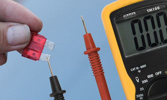
Devices in the form of a small box with a thin internal cable prevent overheating and ignition of circuit elements. Non-wired models are tested like this:
- The device switches to dialing mode.
- The probes are attached to both sides of the fuse.
- With a resistance of 0 ohms and the presence of sound, the device works.
- The number 1 appeared, there is no sound - the fuse is broken.
The breakdown resistance index reaches a large value.
Diodes and LEDs
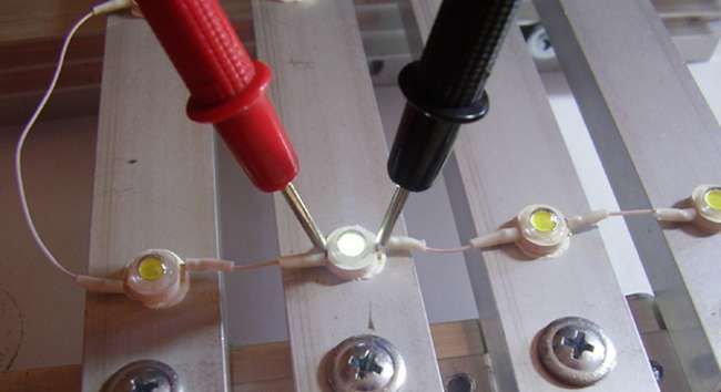
The polarity of the diodes is represented by a positively charged anode and a negatively charged cathode. For this reason, it passes current in only one direction. When testing, the multimeter is transferred to a special mode:
- The probes are placed on the anodes and cathodes without reference to color.
- The tester is activated.
- The probes are swapped and the tester turns on again.
The serviceability of the diode backlight is determined based on the appearance of voltage in the first case and the numbers 1 in the second.
LED polarity is opposite. It works if there is a plus on the anode and a minus on the cathode. The probes work in a similar way. If voltage appears and then disappears, the LED is operational.
Lamps
After putting the tester into the dialing mode:
- Put the first probe on the central contact of the light source.
- Bring the second probe to the side contact.
- The malfunction is determined by the buzzer and an indicator of 3-200 ohms.
With a multimeter, only lamps with a threaded base ring. To test the LEDs and fluorescent lamps, you need to remove the CFL spiral and touch the probes to the terminals on the board.
What readings will the multimeter give after dialing
Cable integrity is checked only at ends with removed insulation coating. After touching the probes to the bare ends, the device will give:
- a sound signal and the presence of 0 on the display or a value close to zero - the whole wiring;
- number 1 on the screen, there is no buzzer - the cable is damaged.
With an internal break, the numerical readings will be in the region of several megaohms.
Checking the integrity of the wiring in the resistance determination mode
You can check the electrical wiring by a device that has no ringing of wires. To do this, select the resistance change mode. The probes pop up by analogy with the continuity and the resistance search mode is set (symbol Ω).
The measurement process starts at the minimum scale value - for example, 200 ohms. The rest of the work is carried out similarly to pinging with tracking of the instrument readings. In the case of the integrity of the conductor, the screen displays the size of the resistance. If there is a break, the data will not be displayed, the device will go into OL mode (reboot).
Using a multimeter allows you to give an objective assessment of the quality of home wiring and the performance of some devices. The minus of the tester is the use only in case of minor malfunctions, serious power line failures should be fixed by specialists.