A non-contact inductance sensor is positioned as a sensor capable of responding to metal objects caught in its electromagnetic field. Due to this property of inductive proximity sensors, it is possible to track the movement of moving parts of the equipment and, if necessary, turn off the motor of the drive mechanism. For recognition and analysis of changes in the magnetic field, a special electronic unit called a controller (comparator) is introduced into their composition.
The device and principle of operation
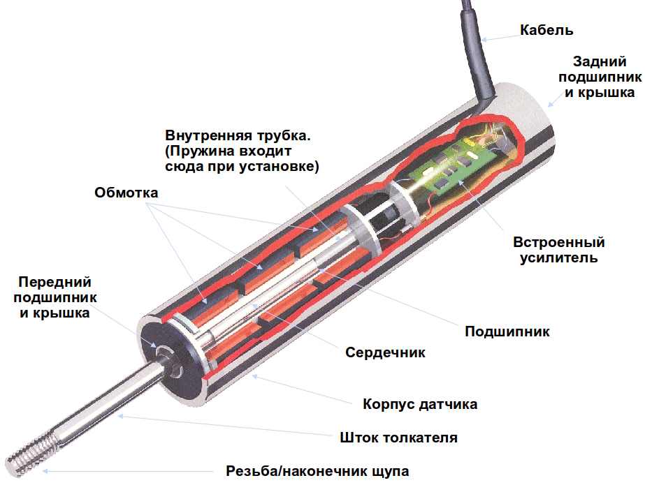
Induction position sensors, in addition to the electronic comparator, contain the following required components:
- steel case with connector for a connecting cord;
- the built-in sensitive element detecting changes in the magnetic field is made in the form of a steel core with a coil;
- executive relay module;
- activation indicator on the LED.
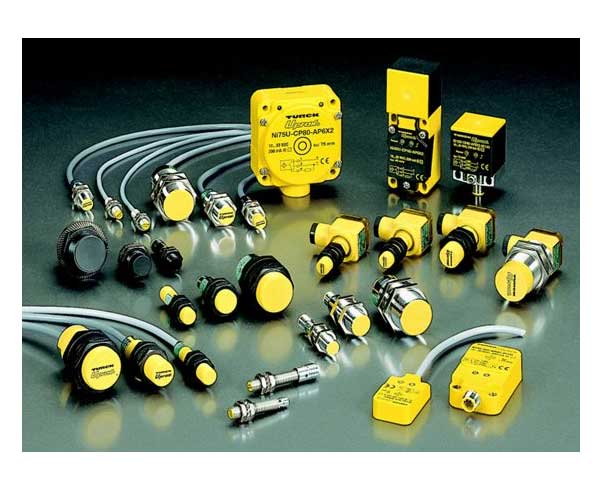
The designs of various models of metal sensors may have some differences. They do not affect the induction sensor itself, the principle of its operation does not change from this.
In accordance with the device device, the essence of its operation is described as follows:
- the movement of the metal part of the controlled object leads to a change in the inductance of the sensor element;
- the deviation is explained by the distortion of its magnetic field, the consequence of which is a change in the parameters of the electrical circuit and its activation (the LED lights up);
- after that, the electronic module is activated and sends a signal to the actuator;
- upon receipt of an impulse about the movement exceeding the permissible limit, the output (relay) node disconnects the controlled equipment from the network.
Each model has its own indicator of sensitivity to displacement - the displacement gap. For various samples, this parameter varies from 1 micron to 20 millimeters.
Inductive Sensor Parameters
In addition to the response range or sensitivity, the inductive sensor is characterized by the following performance indicators:
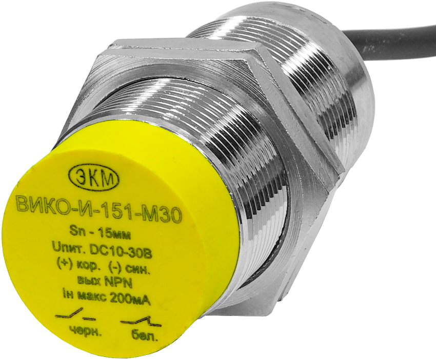
- The size (diameter) of the mounting thread, for various samples, takes values from 8 to 30 mm.
- Rated supply voltage at a temperature of plus 20 degrees, up to 90 volts DC and up to 230 volts - alternating currents.
- The total length of the housing - its value depends on the operating voltage.
The latter indicator for various samples can vary significantly.
For the sensitive or active zone of the device, another parameter is introduced, called the guaranteed response limit. Its lower limit is zero, and the upper one is 80 percent of the nominal value. This indicator is sometimes called the correction factor of the working gap.
An equally important indicator of the functionality of a sensitive device is the number of connecting wires in the connector. Usually there are two or three: two power supplies and one to activate the circuit. However, connection options are possible, in the arrangement of which four or five contact points are used. Such samples except two supply conductors contain two outputs to the load. In this case, the fifth conductor is used to select the operating mode of the device itself.
Types of outputs and connection methods
To evaluate the action of a sensitive device, a special characteristic is introduced, estimated by the state of polarity of its output parameters. In accordance with the generally accepted designation of semiconductor elements (transistors) that are part of the electronic circuitry of the sensor, these outputs are called "PNP" and "NPN".
The difference between these items is that they denote different polarities (poles) of the power supply of sensitive devices. PNP transistors switch its positive output, and NPN - negative. The load of the output circuits is most often the control microprocessor.
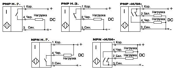
Depending on the control circuit of the controller, inductive sensors are designated as HO (normally open) or HZ - with a normally closed input.
The option with an NPN transistor is the most common way to turn on the sensor, because according to standard circuit solutions, the negative wire is made common to all components. In this case, the inputs of microprocessors and other control devices are activated by positive voltage.
Connection marking
In principle, inductive sensors are usually denoted as a rhombus or square with two vertical lines inside. Often, they also indicate the type of output (normally open or closed) corresponding to one of the varieties of semiconductor transistors. Most circuit designs indicate a normally closed group, or both, in the same enclosure.
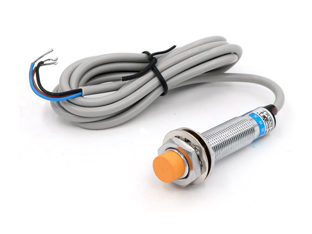
Pin color
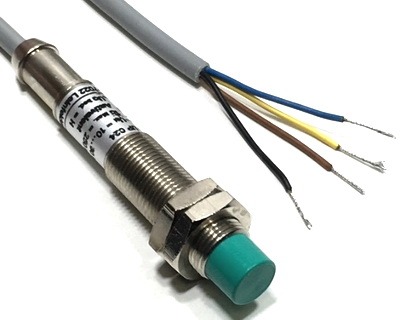
In practice, a standard system for marking the terminals of inductance sensors is used, which all manufacturers of sensitive devices adhere to without exception. Nevertheless, before installing them, it is recommended to carefully monitor the polarity of the connection and be sure to refer to the instructions supplied with the products.
On the cases of all sensors there is a drawing with color marking of wires, if its dimensions allow.
Standard designation:
- Blue always means the negative power rail;
- brown (Brown) denotes a positive conductor;
- black (Black) corresponds to the output of the sensor;
- White is an additional output or input.
To clarify the last marking, it should be checked with the data of the instructions attached to the specific device.
Sensor errors
The error in taking readings by the control system significantly affects the operation of the proximity sensor. Its total value is collected from individual measurement errors for various indicators: electromagnetic, temperature, hardware, magnetic elasticity and many others.
Electromagnetic error is defined as a randomly occurring quantity. It appears due to spurious EMF induced in the coil by external magnetic fields. In production conditions, this component is created by power equipment with an operating frequency of 50 Hz. Temperature error is one of the most important indicators, since most sensors can work only in a certain temperature range. It must be taken into account when designing devices of this class.
The error of magnetic elasticity is introduced as an indicator of the instability of core deformations that occurs during the assembly of the device, as well as the same factor, but manifested during its operation. The instability of internal stresses in the magnetic circuit leads to errors in the processing of the output signal. The error arising in the most sensitive device is manifested due to the influence of the field structure on the strain coefficient of the metal elements of the sensor. In addition, its total value is significantly affected by backlash and gaps in the moving parts of the structure.
The error of the connecting cable is compiled from the deviations of the resistance value of its wire conductors depending on the temperature factor, as well as the interference of extraneous electromagnetic fields and EMF. The strain gauge error as a random variable depends on the quality of manufacture of the winding elements of the sensor (its coil, in particular). In various operating conditions, it is possible to change the resistance of the winding by direct current, leading to the "swimming" of the output signal. The aging error is manifested due to wear of the moving elements of the sensor, as well as changes in the electromagnetic properties of the magnetic circuit.
It is possible to verify the real value of this parameter only using ultra-precise measuring instruments. In this case, the kinematic features of the sensor itself must be taken into account. When designing and manufacturing sensitive elements, this possibility is taken into account in its design in advance.
Inductive and capacitive sensors are characterized by operating modes with many influence factors determined by specific operating conditions. That is why the choice of the sensitivity and the set of output parameters suitable for a given brand of the device is decisive when it is used as a limit switch.