Inductor is an inductor of a certain design and rating, designed for installation in electrical and electronic circuits. The electric inductor must be distinguished from the analogue used in electronic devices, taking into account their design features. To understand what the differences between these two products are, you will have to familiarize yourself with the principle of work and existing varieties.
Principle of operation
The principle of operation of the chokes in the electrical circuit can be explained as follows:
- when alternating current flows through an inductive element, its slew rate slows down, which leads to the accumulation of energy in the magnetic field of the coil;
- this is explained by the action of the Lenz law, according to which the current in inductance cannot change instantly;
- violation of this rule would lead to an unacceptable increase in tension, which is physically impossible.
Another distinctive feature that explains the principle of inductance is the self-induction effect, theoretically justified by Faraday. In practice, it manifests itself as guidance in the coil of its own EMF, which has the opposite polarity. Due to this effect, a current begins to flow through the inductance, preventing the growth of the field formation that caused it.
The specified property allows the use of inductive elements in electrical engineering to smooth out low-frequency pulsations. For them, inductance seems to be a big resistance.
Use in other technical fields (in high-frequency devices, for example), the inductor provides isolation of the main electronic circuit from auxiliary (low-frequency) circuits.
Specifications
The main technical parameter of the inductor in electrical engineering and electronics, fully characterizing its functionality, is the inductance value. In this way, it resembles a conventional coil used in various electrical circuits. And in both cases Henry is taken as the unit of measurement, denoted as Mr.
Another parameter that describes the behavior of the inductor in various circuits is its electrical resistance, measured in Ohms. If desired, it can always be checked using a conventional tester (multimeter). To complete the description of the operation of this element, you will need to add the following indicators:
- permissible (limit) voltage;
- rated bias current;
- the quality factor of the loop formed by the coil.
The specified characteristics of the chokes allow you to diversify their range and use to solve a variety of engineering problems.
Varieties of Chokes
By the type of electrical circuits in which the throttle elements are installed, the classification is as follows:
- low frequency inductances;
- high frequency coils;
- Inductors in DC circuits.
Low-frequency elements resemble an ordinary transformer in appearance, which has only one winding. Their coil is wound on a plastic frame with a core placed inside made of transformer steel.
Steel plates are reliably insulated from one another, which reduces the level of eddy currents.
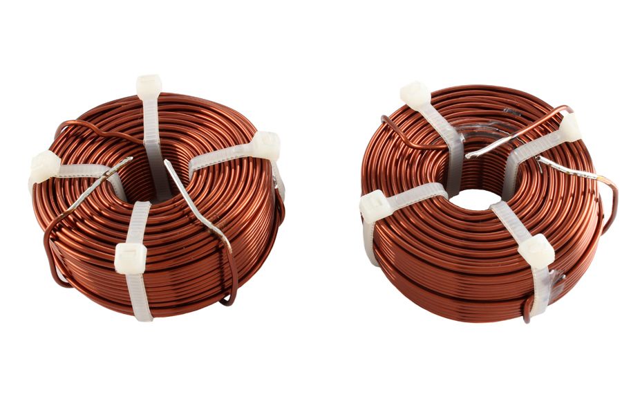
Choke LF coils usually have a large inductance (more than 1 G) and prevent the passage of currents of mains frequencies of 50-60 Hz through the sections of the circuits where they are installed.
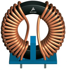
Another type of inductive products is high-frequency chokes, the turns of which are wound on a ferrite or steel core. There are varieties of RF products that work without ferromagnetic bases, and the wires in them are simply wound around a plastic frame. With the sectional winding used in the mid-frequency range schemes, the turns of the wire are distributed in separate sections of the coil.
Electrical products with a ferromagnetic core have smaller dimensions than simple chokes of the same inductance. To work at high frequencies, ferrite cores or from dielectric compositions with a low intrinsic capacity are used. Such chokes are used in a fairly wide range of frequencies.
Some of them are made in the form of a thick twisted wire that does not have a frame at all.
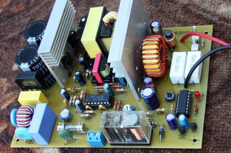
The DC choke is mainly used to smooth out ripples that appear after rectification in special circuits.
The use of inductive elements and their graphic designation
Electric chokes operating in AC circuits are traditionally used in the following cases:
- for decoupling the secondary circuits of switching power supplies;
- in flyback converters or boosters;
- in ballast circuits of fluorescent lamps, providing quick start;
- to start electric motors.
In the latter case, they are used as limiters of starting and brake currents.
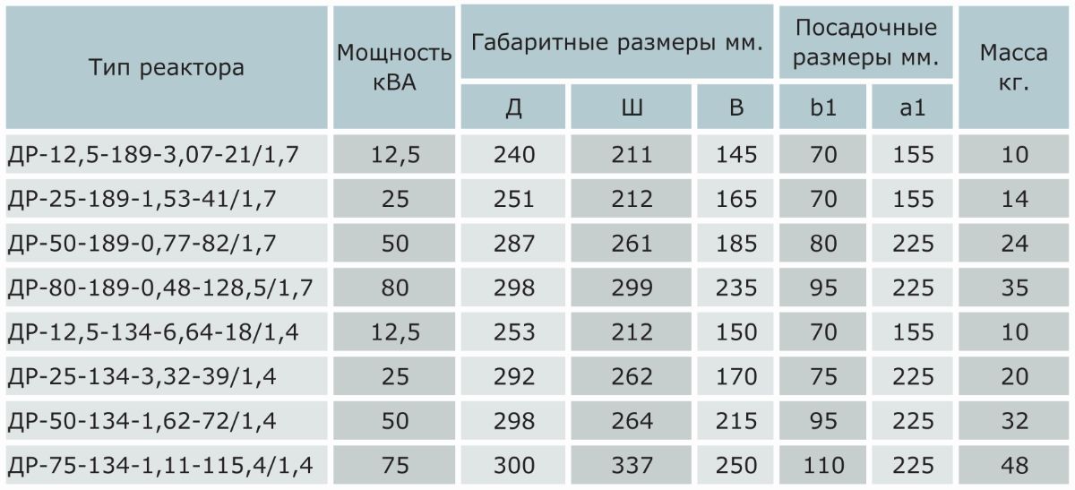
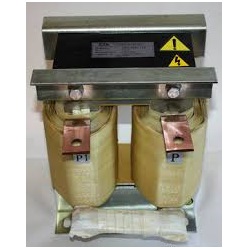
Electrical products installed in electric drives up to 30 kW in appearance resemble a classic three-phase transformer.
 So-called saturation reactors are used in typical flyback voltage stabilizers, as well as in ferroresonant converters and magnetic amplifiers. In the latter case, the possibility of magnetization of the core allows you to change the inductive resistance of the active circuits over a wide range. Smoothing chokes are used to reduce ripple in rectifier circuits.
Power supplies with such elements are still found in electrical practice. To start fluorescent lamps, "electronic" ballast is increasingly being used, gradually replacing winding products. Its use is explained by the following advantages:
- low weight;
- operational reliability;
- lack of buzz characteristic of conventional chokes.
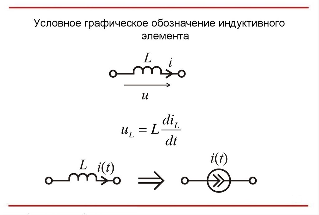
To indicate the throttle on electrical and electronic circuits, icons are used that are a piece of twisted conductor. For coils with a core inside the winding, a dash is additionally put, but in the frameless version it is absent.