A single-line power supply scheme is a document that conveys in graphical form the operating characteristics and design data of the power grid project of a room, whether it is a residential private or multi-apartment building, apartment, garage or enterprise. According to the documentation governing the use of consumer electrical installations, the presence of the circuit in question for a person operating an electric network is a matter of principle, checked during various approvals. Therefore, when designing this document, it is necessary to take into account not only the relevant GOSTs, but also the restrictions imposed by the regional offices of Rostekhnadzor and Energosbyt.
What is a single-line power scheme and why is it needed
 Single-line electrical circuit - a document representing the elements of the power grid of an energy supply facility. It also indicates the technical characteristics of each element and the power indicators of the system (calculated and installed). The goal of creating a linear circuit is to demonstrate the visual configuration of its components and the relationships between them.
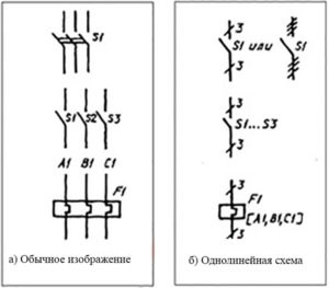
The “single-line” characteristic as applied to power supply circuits means the image of communication channels transmitting energy as one feature, regardless of whether they are single or three phase. This graphical representation allows you to identify power lines and simplify the image of tires and control harnesses equipped with several wires. This makes this type of circuit both concise and informative.
Types of single-line electrical circuits
There are two main classes of schemes that are designed at different stages of the project. To create an OSE, you need to know the key characteristics of each type.
Design scheme
It is designed at the stage of developing documents for the project being implemented. Here, the system characteristics and the required loads are calculated. Settlement documents may include:
- schematic representation of the structure;
- function diagram;
- wiring diagram;
- drawing documents;
- fire safety scheme.
The structure diagram of the electrical equipment shows the power elements (tie-in points, transmission lines, transformer components and others) and the communication between them. A function diagram is created to demonstrate the operation of mechanisms interacting with the power grid and their impact on facility safety. It is usually used for industrial premises dealing with an abundance of heterogeneous equipment. The installation project requires coordination with architectural design decisions and a strict indication of the diameters of the wires and dimensions of the equipment.
The draft design scheme is subject to approval by the city or district authorities for issuing technical specifications for connecting the premises to existing communication networks. The issuance of technical specifications is regulated by regulatory documents.
Executive scheme
It is created when the room has already been used for some time. It is required to graphically display the modifications that are planned to be made to the network structure. The document is prepared when replacing or modifying existing technical equipment. Executive scheme provides information:
- current state of the power grid;
- about electrical appliances included in its composition;
- troubleshooting tips found during technical inspections and other events.
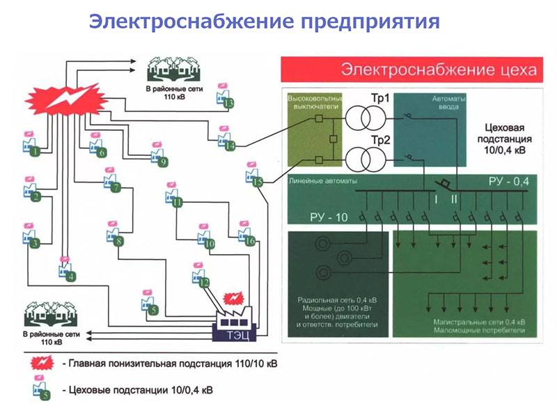
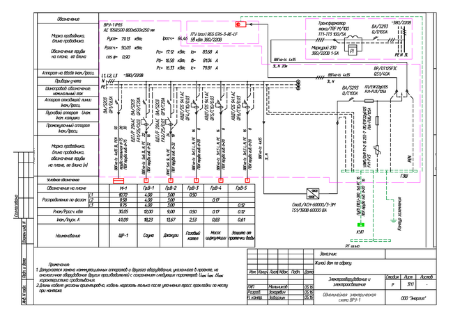
If you need to make a diagram of an enterprise, apartment building or other facility with several supply levels, it is done for each level: for example, for the entire plant, the workshop unit and its individual section. First, an image of the transformer substation and the networks connecting them is made, then drawings for a separate transformer substation or distribution switchboard, and finally, all the individual panels presented in the room.
Design principles
When developing and drawing up the drawings included in the OSE, it is necessary to strictly comply with the rules of the PUE (electrical installation rules), as well as the requirements for this type of work indicated in the regulatory documentation. Before you begin the process, you need to familiarize yourself with the range of circuit elements.
What should include a single-line power scheme
The content of the single-line scheme is regulated by the regulatory documentation submitted to the applicant after considering the request for technical specifications. In the draft scheme should be indicated:
- scope of responsibilities of the supplier and consumer of electricity - they are presented in the text of the contract for the provision of services for the supply of premises;
- the main switchboard and consumer-owned transformer substations indicating the devices for automatically switching on the reserve (if any);
- autonomous power supply (if any);
- data on the distribution cabinets of the lighting equipment and power lines presented in the room;
- horizontal dimensions of the main power lines, models used for cable communication and how they are laid;
- Estimated data on energy loss during transmission;
- information about emergency operation;
- equipment for electricity metering with a designation of the transformation ratio (if a secondary electric current of 5 A is used);
- technical characteristics of fuses, automatic shutdown devices;
- information about loads marked with their power in kW and current strength.
The drawing, developed taking into account the above data, can later be supplemented with additional graphical representations that are not subject to special coordination.
Signatures, according to regulatory sources, should be collected from the following persons:
- specialist who developed the scheme;
- the employee of the bodies who checked it;
- the manager who approved the project.
Initial approval is approved by the person responsible for the electricity supply from the consumer, and the subsequent ones are determined by the characteristics of the premises and the work carried out in it.
Design steps
The stages of developing a single-line circuit have a certain sequence. First, the applicant is required to fill out a request to a company providing electricity services to issue technical specifications for the implementation of this task. After waiting for the documents regulating the process, consumer representatives prepare a draft scheme for these specifications. The developed drawing is agreed with the company that issued the technical specifications.
If during the operation of the power network there is a need to make changes to the configuration of its elements, an executive circuit is prepared. The sequence of steps for her will be identical.
Registration rules, GOST requirements
 When preparing the drawing work for the project under review, it is necessary to strictly follow the standards of the State Standards of the Unified System of Design Documentation that govern the design features of such electrical circuits. Numbers of these state standards:
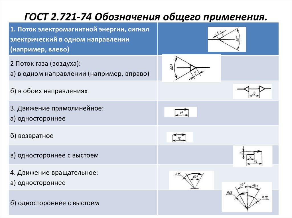
- 2.721-74 - acquaints with graphic conventional signs in schemes;
- 2.755-87 - describes how to designate switching devices and pin connections;
- 2.709-89 - talks about the symbols of wires;
- 2.710-81 - signs that combine letters and numbers.
There are computer applications that allow you to independently develop a scheme corresponding to state standards. A high degree of interface interactivity allows you to get answers to questions that often arise in the process of creating a circuit.
Symbols used in the preparation of single-line diagrams
The visual presentation of the various elements that make up the energy supply system is regulated by regulatory sources. Boxes, shields and cabinets have their own designations in the drawing documents:
- Shields are shown in rectangles. Trunk shield elements have a horizontal line, cutting off a small fragment at the bottom. The group elements responsible for working lighting are filled with black paint, for emergency - they have two diagonals.
- Single panels and cabinets for one-sided service are represented by squares with a horizontal fragment cut from below. Two-way service elements have clippings at the top and bottom. This rule also applies to elements from several panels, only they are presented in the form of the corresponding number of squares arranged in a row.

- The broaching box has a square shape. The intro box appears as a square crossed out by a thick vertical line.
- The branch box is depicted in a circle with a thick transverse line and going down from the center of the circle downwards vertical.
A conventional switch looks like a circle with a line extending from it to the right-up. The number of poles (one, two, three) is shown by the number of small vertical bars at its end. If an open installation is supposed, dashes are drawn from the base right-down, and in the case of a hidden one, it intersects with transverse lines. Double and triple elements will have two or three instead of one line. A high degree of protection is demonstrated by painting the circle black. If the element works in two directions, a second line is drawn left-down from the circle.
The socket is shown as a “lying” semicircle with a line extending from the top up. The presence of two poles is described by a second similar feature, protective contact - additional horizontal, hidden installation - going from the center to the top. Strong protection is shown by shading in black.
Designations of lighting devices:
- Lamps with fluorescent lamps show elongated rectangles, the rest of the devices - circles.
- The cable is depicted by a transverse dotted line and a thick line under it near the "equator" of the circle.
- Outdoor lighting devices show the letter “T” tilted to its side, growing from the left side of the circle.
- The chandelier is shown by dividing the circle into 6 segments.
- The tube wall cartridge is a blackened triangle with a V-shaped fork on top.
- Suspension cartridge - circle crossed out by diagonals. Ceiling - similarly, but strikethrough elements within the figure are not applied to the image.
- Ammeter, voltmeter, galvanometer - figures are round in shape, with the letters A, V and an upward pointing arrow inside, respectively.
- Temperature sensor and oscilloscope - squares. The first one has the t icon inside and the arrow pointing to the right coincides with the base. The second has a thin N-shaped image of lightning.
- Electricity meter - a high rectangle with a separated upper segment and the inscription Wh.
If the developer of the scheme has doubts about how to depict one or another element, he can familiarize himself with the nomenclature of OSE symbols in the reference literature.
Programs for execution of executive documentation
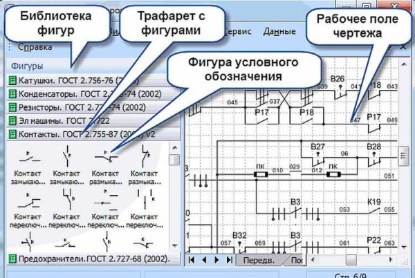
For the preparation of high-quality documentation in accordance with state standards, there is no need to draw the diagram by hand on paper. It can be drawn online using the software sharpened for this purpose.Examples of such applications:
- MS Visio - is widely used for all kinds of office work and is suitable for preparing a drawing of an electrical diagram of a residential building;
- Compass-Electric - a simple program distributed freely used by employees of power supply services;
- 1-2-3-Scheme - an option often chosen by students and inexperienced specialists;
- AutoCAD Electrician is a popular program among professional developers.
Choosing the right program is based on the scale and complexity of the network. For example, for a private home there is no need to use complex professional software.
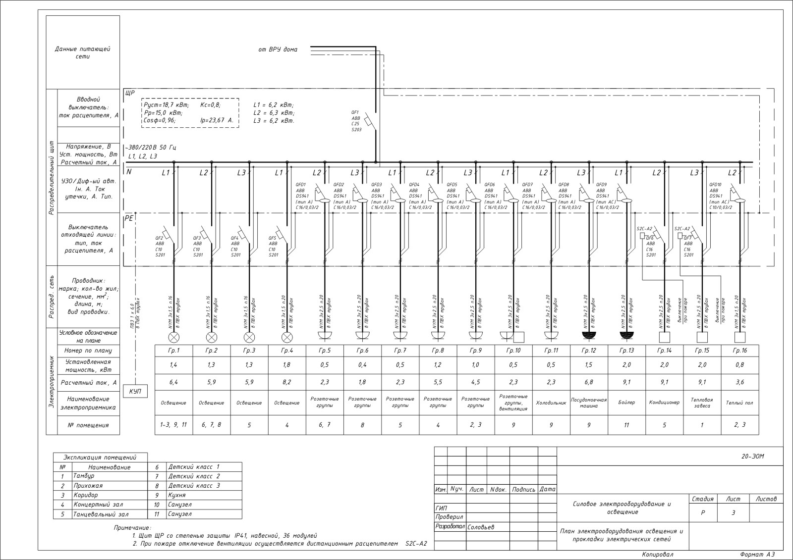
When performing this task independently, it must be remembered that the drawing should clearly represent the main parameters of the power grid. You can download a sample of a single-line power supply scheme from the Internet, make the necessary adjustments and check for compliance with state standards. The image should contain three phases, powering the room, outgoing from them the power lines of group networks, data on switches and residual current devices, power cables.