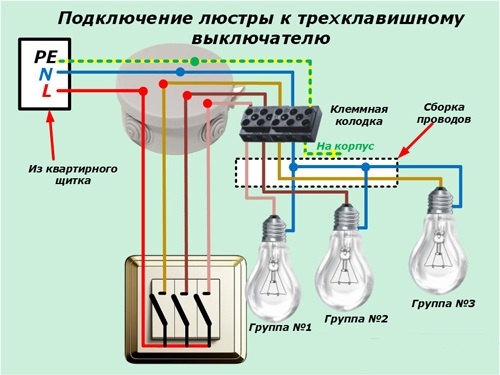
When arranging a home wiring or repairing it, you need to know exactly how to connect a three-button switch to an existing lighting network. It follows from how many light fixtures are supposed to be used in this line and how to rationally distribute the three key mechanisms for individual loads. To understand how 3 key switches are connected, you will need to familiarize yourself with their design and application specifics.
Design and application features
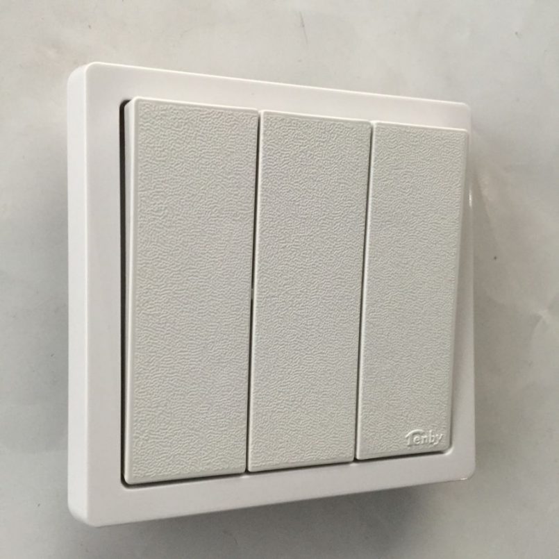
Structurally, the 3-key switch is a standard flip type mechanism consisting of three identical nodes. When changing the position of one button-key (when pressing it to the upper edge), the internal switch closes this chain. When pressing on its lower part, the system returns to its original state when the electric circuit is open.
The same processes occur when you press the remaining two keys of a three-button device.
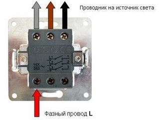
The design feature of this mechanism is that its lower contacts are combined into one block, to which a common phase wire is supplied. And the upper terminals are made separate, which allows you to connect three different loads to them.
The standard connection of a 3-key switch assumes the following switching options:
- When one of the keys is pressed, the phase voltage is applied only to the circuit extending from the corresponding contact to the load side. A separate lamp or group of illuminators is connected.
- If you press two buttons at once - 220 Volts are switched to wires that are connected to two lamps of the chandelier, for example.
- When all the key mechanisms are moved to the upper position, the phase enters immediately into three load lines with the lamps turned on.
After moving the entire cross over system to the lower position, the voltage from the upper electrical contacts of the switch is completely removed. All bulbs of the chandelier controlled by it go out.
The three-key switch can be turned on in different ways and can be activated either partially or fully. The latter case is in demand, if necessary, to increase the illumination of the room to the maximum.
Order and schemes of inclusion
The procedure for laying and connecting conductors suitable for the circuit breaker depends on how it is included in the circuit. According to the schemes used to connect the light switches with three keys, the following options are possible:
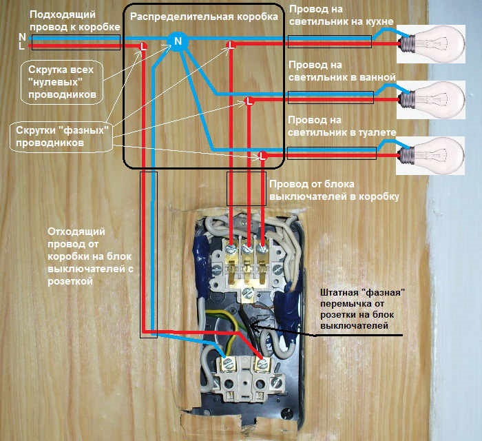
- Only a phase conductor connected to three different loads is supplied to the device. A zero wire is laid to the chandelier from a nearby junction box at the construction stage.
- For connection, a phase wire is used, going along with the zero core from the nearest outlet.
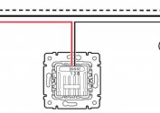
In the first case, the lead wire is walled into the wall (with hidden wiring), and its end protrudes outward. Its length should be sufficient so that you can connect the end to the common terminal of the switch. Three outgoing conductors are laid along the wall surface to the appropriate load through the junction box.
The second method is used when connecting triple switches with a socket in old houses, where full-fledged junction boxes are most often missing. In their place under the ceiling is a plastic box with twists placed inside.
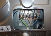
In this scheme, both phase and zero are taken from the outlet, and the latter is laid around the circuit breaker and, together with the phase conductor, connected to the existing twist. From there, they are intersected together on a lighting fixture. When making connections in a junction box or twisting, you must carefully monitor the insulation color of the conductors that are suitable and extending towards the lamp.
Zero conductors usually have a blue (blue) insulation, and the protective coating of the phase conductors in color is either red or brown. Switching a pair of power contacts is carried out strictly in compliance with color marking.
Regardless of the circuit in which you want to connect the switch, it can be used for the following needs:
- Connect a separate chandelier with three or more groups of lamps.
- Switching operation of spotlights or backlight elements (based on LED strip, for example).
- Lighting control in three rooms from one remote place (for this purpose a corridor is usually selected).
The main of the proposed options should be considered in more detail.
Connecting a chandelier and three rooms
When connected to a three-gang switch of a chandelier operated in a particular room, the following methods of switching individual lamps are possible:
- Voltage is applied to each horn from one of the upper contacts of the push-button device, which allows them to be switched on individually or together.
- If desired, three bulbs can be switched according to various schemes (“1 plus 2”, for example), one combination is switched on from one contact, and the other from the second.
- The inclusion practiced when using 5, 6 or more bulbs in the chandelier. All of them are divided into groups.
When controlling lighting in three adjacent (not aisle) rooms in an apartment or a private house, the switch is placed in a common corridor near its exit. In this case, the lighting is switched on as necessary in one of the rooms, in two rooms or in all at once.
Connection errors
Before replacing the three-key type switch in your apartment, it is advisable to familiarize yourself with the characteristic errors made during this operation. The main violations in connecting a new device:
- The phase wire is supplied not from below, but from above the switch, which is considered unacceptable and will require alteration.
- The switch is not built into the phase line, but into the zero circuit. This is a gross violation of the PUE requirements and can lead to an accident (electric shock).
- The wires extending from the switch are connected to the lighting device not directly through the junction box, but directly.
The latter violation will lead to the inconvenience of the redistribution of individual lighting groups when the need arises, for example, when repairing or replacing a chandelier.
When using a three-key device for switching lighting in three rooms, it is sometimes mistakenly installed on premises of a passage type. For "through" rooms, this type of connection is not suitable; special through-type switches will be required.