Modern energy supply systems are built on the basis of standard schemes that take into account the grounding methods of equipment connected to them. This is done in order to protect the end user, as well as personnel working on electrical installations. When organizing modern networks, cables are traditionally used that include not only a phase core, but also a working zero N, as well as a protective PE conductor. In some cases, these two types of tires are combined into one common PEN core. To understand their functionality, you first need to find out what the PE bus is and how the other conductors are color-coded.
Types of grounding systems
 Known electrical protection systems differ in a number of ways, according to which they are divided into the following types: TN-S, TN-C, TN-C-S, TT, as well as IT. The icons included in these symbols are decrypted as follows:
- T means grounding (from the French "Terre" or ground).
- N is the connection to the transformer neutral.
- I means isolated.
- C - the combination of the functions of the working and protective neutral conductors ("common").
- S - separate use of these cores ("select").
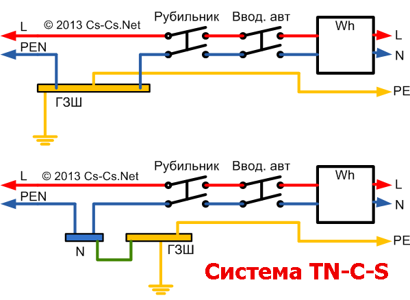
According to the PUE, TN-C means a neutral grounded system with combined protective and working conductors.
The designation TN-C-S means that at some point in the power circuit, two conductors are laid together, and then they are separated by a functional attribute.
Zero tire classification
According to the functions performed, the zero buses included in the power supply system are divided into the following types:
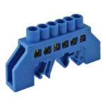
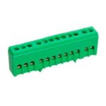
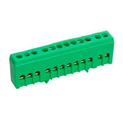
- N - functional or working "zero", which is a conductor for load currents.
- PE - specially laid protective "zero", providing the possibility of organizing grounding at the receiving end in a convenient place.
- PEN is a conductor combining the functions of both of these buses.
-
- N

-
- PE
-

- PEN

Each of the conductors in the circuits is highlighted in a specific color (N - blue, PE - yellow-green, and PEN - their combination). They must be selected according to their cross section, which should not be less than the same indicator for phase buses.
This decryption also allows you to understand why you need to separate the PEN conductor, what it serves for, how you can arrange grounding on the consumer side.
Why divide PEN into two parts
It makes sense to separate the PEN wire into PE and N conductors only if each of them is supposed to be used for its intended purpose. This can be done in the following cases:
- in a private (suburban) house, when in the switchboard a tap is made from the PE bus, used to organize local re-grounding;
- in the city apartment building, where the residents of the entrance agreed to equip a common grounding circuit on the street next to the entrance;
- copper descent is conducted from the PE wire to a homemade ground loop.
For the implementation of grounding with a self-made circuit, a permit from the relevant energy services and coordination with the housing and communal services will be required.
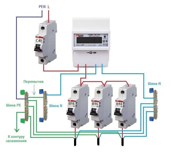
When a jumper is placed between the tires in city houses in the dashboard, there is no need to talk about full grounding. The regulatory documentation on this subject gives a recommendation without a detailed explanation of the effect of such a "grounding".
Conductor splitting options
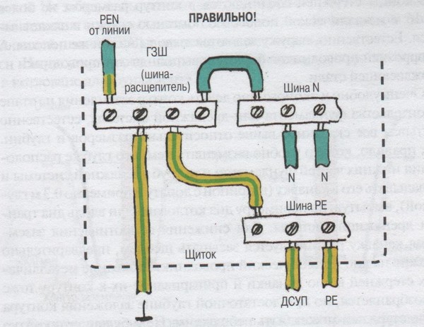
In the switchboard, where the PEN conductor is separated, grounding is organized by the splitting method, but a jumper must be installed between N and PE.It is important that the ground bus is connected first, and only after that the connection of the working core is made out. In this situation, there are four options for turning on the PE wire:
- There is no jumper between it and conductor N - the working zero contact and the grounding bus are not electrically connected. An RCD in the protective circuit is also not set.
- There is a jumper between these terminals, but an RCD is not installed.
- PE for grounding and N shorted and installed RCD.
- There is no jumper, but there is an RCD.
In the first case, the “physics” of the operation of protective circuits looks like this:
- The emergency phase enters the instrument housing.
- Then it goes to the ground bus.
- Further along it goes to the circuit of the transformer substation.
When considering the problem, it is important to consider the resistance of the grounding chain, usually not exceeding 20 Ohms, taking into account the cross section of the PE conductor in mm. square. In the event of an accident, the short circuit current will not be enough to turn off the input circuit breaker. The protective circuit will operate until the damaged area on the receiving side has completely burned out. This situation will not be able to bring significant harm to a person, but the equipment will receive serious damage (the worst option is its fire and fire).
There is a jumper, there is no RCD
In this case, an important role is played by the length of the supply line (removal of the place of damage from the input-distribution electrical panel), which determines the resistance of the wire to drain the charge. In the event of an emergency phase closure on the case of damaged equipment, the leakage current first enters the grounding bus. Then he has only two ways: part of the emergency electricity goes into the ground, and the other on the zero bus will trigger the machine at the input. In this situation, the jumper is used in case AB has failed for some reason. But since the latter is practically impossible, there is no difference whether it is or is absent.
The jumper is and is installed RCD
Since all protective and working conductors have a certain resistance, in this case, the RCD should operate normally. When a short circuit is formed on the housing, the leakage current first flows to the RCD itself and only after that it goes to the input of the residential building. Here, as in the previous case, it is divided into two parts: some part of the whole goes into the ground, and part through the jumper returns to the shield, turning off the opening machine. However, as a rule, this does not come to this, because the RCD works much faster.
In this situation, the jumper does not have much significance and is only a safety net just in case: if, by a strange set of circumstances, an RCD will not work.
No jumpers and UZO installed
Such a circuit will work the same as with a jumper. The only difference from the previous case is the lack of insurance in case of failure of the RCD, which is unlikely. If this still happened, the scheme will begin to work out according to the first of the options considered. In this case, the input device does not work until the short circuit to the case is transformed into a phase short circuit.
Typical phase splitting errors are associated with disturbances in the commutation order. You can not connect the working core first and only after it connect the ground. Another common mistake is the reluctance to install an RCD. In circuits with artificial splitting of the PEN conductor, a residual current device is mandatory.
Features of separation of the PEN conductor
In private homes and in city apartments, in order to prevent theft of electricity, representatives of the controlling organization have the right to demand that the PEN wire be extended to the meter. And only after the metering device they allow it to be divided into a protective bus PE and a working N. Such a connection does not contradict the requirements of the PUE, but the separation performed before the meter looks much more natural.
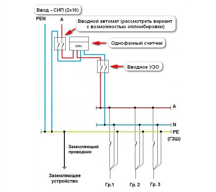
If you first make a separation, and then seal the introductory machine, there can be no objection from the representatives of Energosbyt and inspectors.