Given the wide variety of electrical equipment installed in power circuits, it is important to learn how to properly operate power supply systems and maintain them in working condition. Violation of this requirement leads to a decrease in performance and the possibility of damage to devices connected to it. Checking the conductive lines involves the organization of testing, which includes the measurement of distributed electrical parameters. During periodic tests, all protective devices and electrical conductors, as well as the so-called “phase zero loop”, must be examined.
Definition of a concept
Any equipment connected to the mains is equipped with a protective grounding circuit. This device is equipped in the form of a prefabricated metal structure located either next to the controlled object or at a transformer substation. In the event of an emergency (if the insulation of the wires is damaged, for example), the phase voltage falls on the grounded housing, and then flows into the ground.
For reliable spreading of dangerous potential into the soil, the chain resistance should not exceed a certain norm (Ohm units).
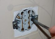
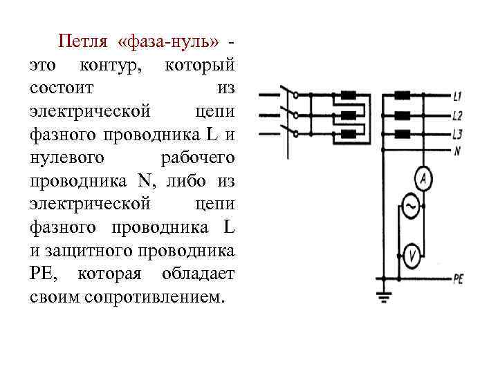
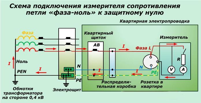
A phase zero loop is understood as a wire loop formed when a phase core is shorted to a conductive case of equipment connected to the network. In fact, it is formed between the phase and the grounded neutral (zero), which was the reason for this name. It is necessary to know its resistance in order to monitor the state of the protective grounding circuits that ensure the emergency current to drain into the ground. The state of this circuit determines the safety of a person using equipment and household appliances.
Method for determining the resistance of the phase-zero loop
 In accordance with the requirements of PTEEP, the operation of industrial and domestic electrical equipment requires constant monitoring of the status of protective devices. According to the requirements of normative documentation in installations up to 1000 Volts with a grounded neutral, they are checked for a single-phase short circuit to the ground. Known test methods primarily take into account the technical base represented by samples of special measuring instruments.
Used equipment
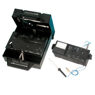
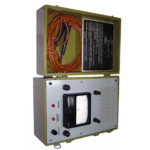
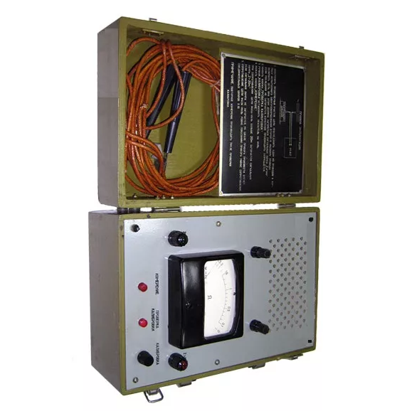
To measure the phase-zero chain, electronic devices are used that differ in both their capabilities (the method of taking readings and their error, in particular) and their purpose. The most common meter examples include:
- Instruments M417 and MSC300, allowing to determine the desired value, at the end of the measurements, the short-circuit currents to earth are calculated based on the results.
- The ECO-200 device, by which it is possible to measure only the fault current.
- The device EKZ-01, used for the same purposes as EKO-200.
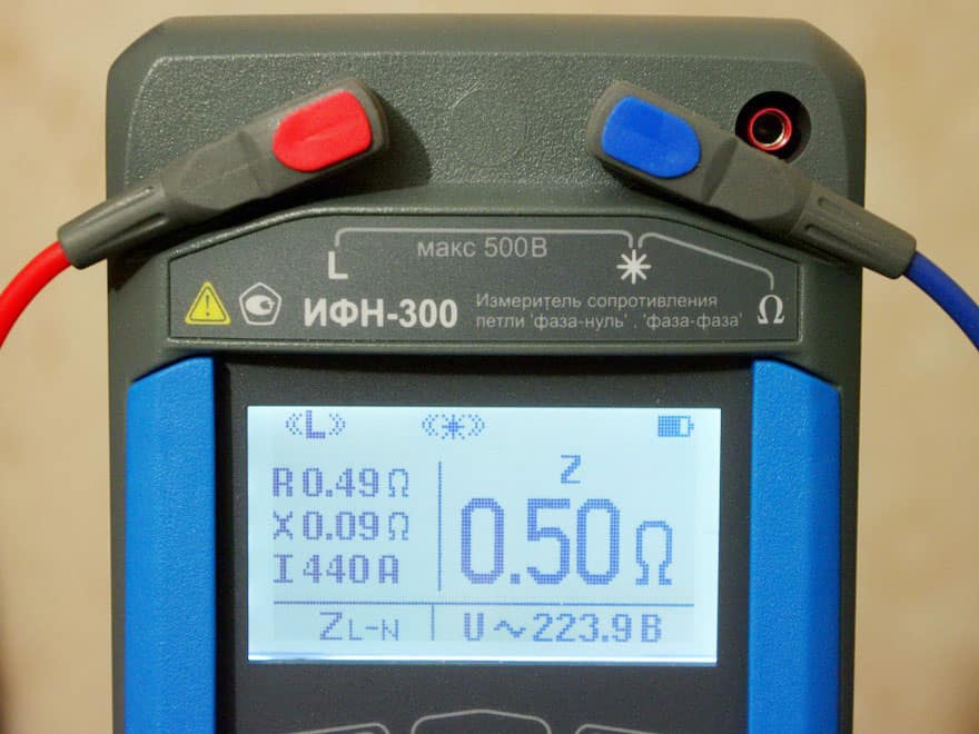
- IFN-200 measuring instrument.
-

- IFN-200

-

- ECO-200
-
- M417
The M417 device allows measurements in 380 Volt circuits with a grounded neutral without the need to remove the supply voltage. When conducting measurements, the method of its fall is used in the mode of opening the controlled circuit for a period of time of 0.3 seconds. The disadvantages of this device include the need to calibrate the system before starting work.
The MSC300 belongs to a new type of product with electronic filling built on modern microprocessors.When working with it, the potential drop method is used when connecting a fixed resistance of 10 ohms. The operating voltage is 180-250 Volts, and the measurement time of the controlled parameter is 0.03 seconds. The device is connected to the tested line at its farthest point, after which the "Start" button is pressed. The measurement results are displayed on the digital display built into the device.
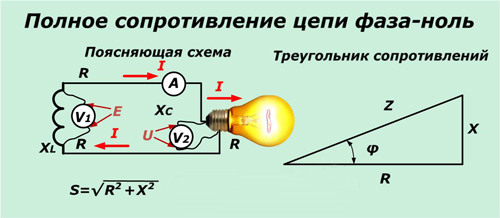
When there is not a single sample of the measuring device available (and also, if necessary, duplication of operations), for practical determination of the desired value, a measurement method using a voltmeter and ammeter is used.
Existing Measurement Techniques
 Known techniques include the calculation part, presented in the form of formulas. A common calculation tool allows you to find out the total loop resistance using the following formula:
Zpet = Zп + Zт / 3, where
- Zп - impedance of wires in the KZ section;
- Zt is the same, but for a power transformer of a substation (current source).
For duralumin and copper wires, Zpet is on average 0.6 Ohm / km. The resistance found is the current of a single-phase earth fault: Iк = Uф / Zпет.
If, as a result of the above calculations, it turns out that the value of the desired parameter does not exceed one third of the permissible value (see PUE), we can limit ourselves to this calculation option. Otherwise, direct current measurements are carried out using the ECO-200 or EKZ-01 devices. In their absence, the method of an ammeter-voltmeter can be used.
 The general procedure for testing using measuring instruments of the indicated brands:
- Controlled equipment is disconnected from the network.
- The tested loop is powered by a step-down transformer.
- It is necessary to deliberately close the phase on the body of the electrical receiver, and then measure the value of Zpet resulting from the short circuit.
When measured by the method of an ammeter-voltmeter, after applying voltage to the controlled circuit and arranging a circuit, the current I and potential U are determined. The first of these values should not exceed 10-20 Amps.
Calculations and presentation of results
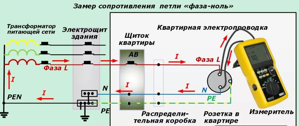 The resistance of the tested loop is calculated by the formula: Zpet = U / I. The value obtained from the calculation results is added up with the impedance of one of the 3 windings of the station transformer equal to Rtr. / 3.
Upon completion of linear measurements in accordance with applicable standards, they should be documented. To do this, in accordance with the established form, test reports are prepared in which the following data is necessarily recorded:
- Type of line, its main characteristics.
- The measuring equipment used in the verification.
- Values of own transient resistance and windings of a station transformer.
- Their amount, which is the result of the measurements.
In accordance with the main provisions of the PUE, the frequency of inspections on power circuits is once every 6 years. For explosive objects - once every two years.
Table calculations
 The full value of the desired value depends on the following factors:
- Parameters of power substation transformer.
- The sections of the phase and zero conductors selected during the design of the electric network.
- The resistance of transition compounds, always available in any circuit.
The conductivity of the wires used can be set even at the design stage of the power system, which, provided that it is correctly selected, will avoid many troubles.
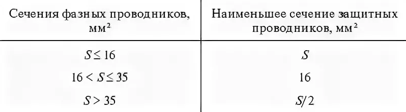
According to the PUE, this indicator must correspond to at least half of the same value for phase conductors. If necessary, it may be increased to the same value. The requirements of chapter 1.7 of the PUE stipulate these values, and you can familiarize yourself with them in Table 1.7.5, given in the Appendix of the Rules. According to it, the smallest cross-section of the protection conductors (in millimeters square) is selected.
Upon completion of the tabular stage of the calculation of the phase-zero loop, they proceed to its verification by calculating the short circuit current according to the formulas. Its calculated value is then compared with practical results obtained earlier by direct measurements. With the subsequent selection of short-circuit protection devices (linear circuit breakers, in particular), their response time is tied to this parameter.
In what cases do measurements
 Measurement of the resistance of the phase-zero circuit section is necessarily organized in the following situations:
- when putting into continuous operation new, not yet working power installations;
- when the direction of their implementation was received from the controlling energy services;
- according to the application of enterprises and organizations connected to the served electric network.
When the energy system is put into operation, test measurements of the loop resistance is part of a set of measures taken to verify its performance. The second case is associated with emergency situations, which often occur during the operation of power circuits. An application from certain consumers submitted by an enterprise or organization may come in case of unsatisfactory protection of the equipment (based on complaints from specific users, for example).
Examples of calculations
Two methods are considered as examples of such measurements.
The effect of a voltage drop in a controlled section of the power circuit
 When describing this method, it is important to pay attention to the difficulties of its practical implementation. This is because in order to obtain the final result, several steps will be required. First, you will have to measure the network parameters in two modes: with disconnected and connected loads. In each of these cases, resistance is measured by reading current and voltage. Further, it is calculated according to the classical formulas arising from Ohm's law (Zп = U / I).
In the numerator of this formula, U represents the difference between the two voltages - when the load is on and off (U1 and U2). Current is taken into account only for the first case. To get the correct results, the difference between U1 and U2 must be large enough.
The impedance takes into account the impedance of the transformer coil (it is summed with the result).
The use of an independent power source
This approach involves the determination of a parameter of interest to specialists using an independent source of supply voltage. When conducting it, you will need to consider the following important points:
- During measurements, the primary winding of the supply station transformer is short-circuited.
- From an independent source, the supply voltage is supplied directly to the fault zone.
- The phase-zero resistance is calculated by the familiar formula Zп = U / I, where: Zп is the value of the desired parameter in Ohms, U is the measured test voltage in Volts, I is the value of the measuring current in Amps.
All the considered methods do not pretend to absolute accuracy of the results obtained based on their results. They give only a rough estimate of the impedance of the phase-zero loop. This character is explained by the impossibility of measuring the inductive and capacitive losses, which are always present in power circuits with distributed parameters, within the framework of the proposed methods. If it is necessary to take into account the vector nature of the measured quantities (phase shifts, in particular), special corrections will have to be introduced.
Under actual operating conditions of powerful consumers, the values of distributed reactance are so insignificant that under certain conditions they are not taken into account.