The increase in household appliances in modern apartments provides for the systematization of the line load, the division of the circuit into group circuits. These actions protect against network outages and emergencies while turning on multiple high-power devices. The switchboard in the apartment allows you to organize power circuits, meters, circuit breakers. With knowledge of electrical processes and the ability to work with tools, you can assemble the box yourself.
Normative documents and rules
Shield - switchgear operating under voltage up to 1 kW. Its features are considered in Ch. 4.1. 7th edition of the PUE. The requirements for the ASU in a multi-storey residential building are specified in GOST 51732-2001, and for switchboards in GOST R 51628-2000. Since the apartment electrical panel belongs to the low-voltage distribution and control apparatus, it is required to refer to GOST 51321.1-2007.
Basic requirements and installation rules
In GOSTs and PUE the correct way to connect the shield is indicated.
Standards note several points:
- the presence of a complete circuit with a rating of the circuit breaker, type and cross-section of the cable, installed and one-time power, protection parameters of the shell;
- allowed the installation of modules equipped inside or outside with a nameplate;
- obligatory drawing of the “Caution of voltage” sign in the form regulated by GOST R 12.4.026;
- selection of cable cross-section for laying inside according to the rating of circuit breakers;

- selection of wire insulation capable of withstanding AC voltage of at least 660 V;
- protection of bolted joints from vibrations and short circuit with cup springs, controllers, spring washers, tips;
- assembly of neutral conductors on the N and RE buses;
- connecting the REN wire to the RE shield;
- the use of terminals to protect the input and output wires;
- performance of work with screwdrivers with slots under the slot of screws, tools with insulated handles;
- cable marking with colored PVC tubes - blue / blue (working zero), yellow-green (zero protection), red / brown (phase);
- marking of bus contacts N and RE according to the serial numbers of circuit breakers;
- one conductor connection per N or RE bus terminal;
- designation of outgoing cables round (line voltage from 1000 V), square (voltage up to 1000 V), triangular (control) tags.

Bus N and RE, separated in the power wire, must not be combined.
Which case is more reliable - made of metal or plastic
The housing shield is available in a metal and plastic case. The choice of material depends on the project, terms of reference for design and financial capabilities of the user.
A metal switchboard has a number of features:
- reliable landing on a protective zero;
- high anti-vandal characteristics;
- good fire resistance;
- installed on the street or in the entrance;
- moisture resistance class IP31 - IP54.
The minus of the metal case is the need for grounding. The third wire will need to be removed from the main power board of the apartment.
The plastic case has the following characteristics:
- Suitable for interior design;
- can be embedded in a special niche;
- resistance to wet environment;
- beautiful transparent or tinted door;
- excellent dust resistance.
With poor insulation, there is a risk of fire in the plastic and fire. In this case, it is better to purchase a box made of PCB.
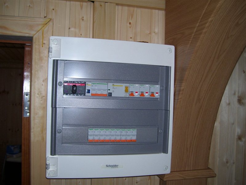
Regardless of the material of the case, you can choose a shield for installation in the apartment on 12-72 modules.
Electrical panel elements
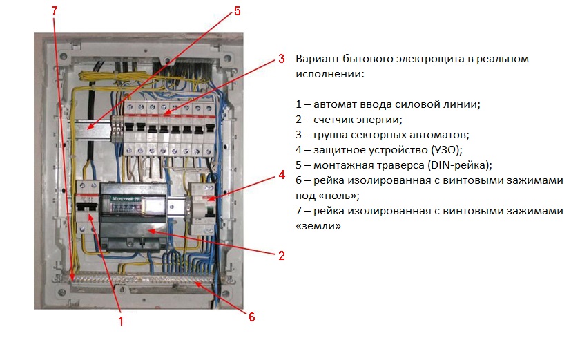
The apartment panel consists of the following units:
- Circuit breaker. A two-row device is placed at the input and can disconnect the zero and phase wires.
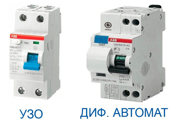
- RCD It is a differentiated type relay. It is necessary to quickly de-energize the line when a voltage leak occurs.
- Additional circuit breakers that control the circuit with powerful appliances - electric stove, washing machine, water heater, air conditioning.
- Zero and ground buses. Dielectric base copper strips ensure the safety of the ground contact and the working neutral.
- Body. It contains all the nodes. It happens metal, plastic. By the method of installation, there are mounted and built-in models.
- DIN rail A metal plate fixed to the body. Automata are mounted to it with special fasteners.
- Connection cables with a cross section corresponding to the power rating of the equipment.
The outdoor box should not pass current, so it is better to buy models made of heat-resistant plastic or metal with a polymer coating.
What should be in the electrical panel
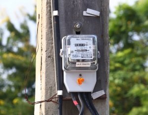
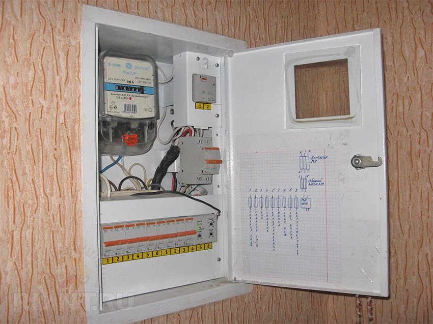
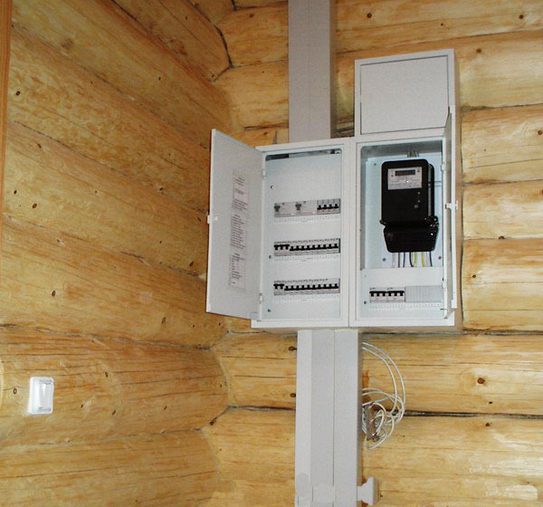
The layout of the switchboard in an apartment or a private house is of several options. The main difference is the presence of a counter and an automatic machine at the input. In private homes, meters are placed on a pole, and machines are on a wall. The meter can also be located inside the house, and then a shield is required.
In apartment buildings, electrical boxes are installed on a stairwell. In this case, the cabinet is required for RCDs and machines. Installation inside the apartment is also allowed, but this requires a compact and roomy product.
The nuances of choosing modular equipment for the electrical panel
Before you put an electric panel in the apartment, you will need to make its circuit and coordinate with the company energy sales. The drawing indicates each module and its purpose. In the process of selecting devices, the following points should be considered:
- Application of modules of one manufacturer and one series. Depending on the manufacturer, the width of the modules varies by a few millimeters. The difference leads to a mismatch of parts.
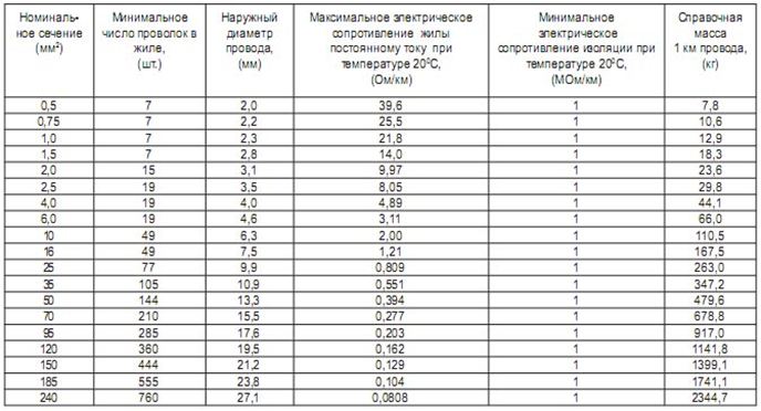
- The cross-section of the PuGV installation wire is selected for the cross section of the input cable. Optimum - from 4 to 6 mm2.
- To mark zero, earth and phase, you need a thermotube of white, black, red (phase) and black (working zero) color.
- Busbar combs with one to three strips will provide the connection of modular devices. End caps will also be needed for the combs.
- For each group RCD, you will need a separate zero bus or cross-modules with good isolation.
- The DIN rail limiter eliminates the spread of a number of modules to the sides.
- Plugs are used to close the cavities formed in the shield.
To fix the wires inside the shield, you should buy plastic clamps.
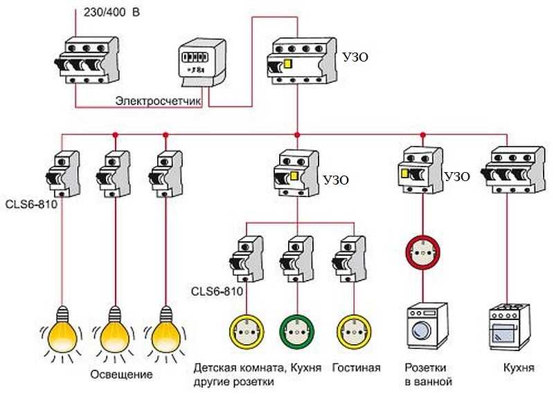
Variant of a simplified diagram of an apartment shield
You can independently assemble a small electrical panel and install it in the apartment. In order not to get confused, it is worth choosing the simplest scheme possible. It must comply with the requirements of GOST 32395-2013.
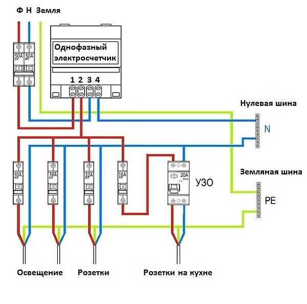
The scheme of the electric apartment panel presented below is advisable to apply to a one- or two-room apartment with a total cable length of 300-400 m. The work is carried out as follows:
- An input voltage switch is installed with a current rating of 40 A, if the apartment has a single-phase type of load and there is an electric stove.
- The wires are wired into groups, the brand and type of cable section are indicated.For lighting, a cable of 1.5 mm2 and an automatic machine of 10 A will be optimal; for outlets, a wire of 2.5 mm2 and a device of 16 A.
- The bathroom can be connected to a difavtomat with a current leakage of 10 mA, combining consumers and lighting in one group.
- The hob and oven are powered as two different consumers.
- To protect against voltage fluctuations and equipment malfunctions, you can choose a voltage relay with a simple connection system (phase + zero at the input and output).
The advantage of the scheme is the low cost of nodes, the possibility of use in a small apartment. The minus of exclusion is the absence of protection operation during current leakage in all groups, except for the bathroom.
Schematic diagram with an RCD for individual groups
The RCD device operates at a load of 1 A to 80 mA, which prevents electric shock and death in cases of leakage. The device is suitable for residential premises, where the wiring has a total length of 400 m.
The apartment can be turned off as follows:
- Installing the device at the input. An RCD with a response limit of up to 30 mA is suitable for an apartment with a single-phase load of 11 kW.
- Protection against current leakage is also placed on the outlet lines and the split system group.
- One device is located on a joint system, where a circuit breaker is installed on each group.
- Installation of a standard machine for a network with metal housings for lighting fixtures.
Each RCD must be put on a separate bus.
Build and Connect Algorithm
Regardless of which shield design is selected, assembly activities are carried out sequentially. They are made only in a clean and dry room.
Body installation
Mounted models are placed on special hardware, and built-in models in a niche. Boxes may be collected in a well-lit room at the exit. The humidity of the room should be 15%, the distance to the nearest ledge - 15 cm, to the gas pipeline - from 1 to 1.5 m, from the floor - not lower than 1.4 m and not higher than 1.8 m.
Further assembly instructions for the embedded model include the following:
- Marking with the help of the level of the site where the electrical panel will stand. A line is drawn along the edge of which the housing is applied and encircled.
- Perform grinder cuts according to the drawing. The disc should plunge into the wall 1/2.
- Punching a niche with a chisel or perforator along the thickness of the box.
- Checking the compliance of the dimensions of the body with the depth of the niche
- Installing a standard mount on the body, marking the screwing points of the screws.
- Drilling holes for fasteners with a puncher.
- Installation of a DIN rail with modules.
- Filling cavities with foam.
If fasteners are not included with the mounted model, it can be nailed to the wall with dowels. To strengthen the fastening, the box sits on the alabaster.
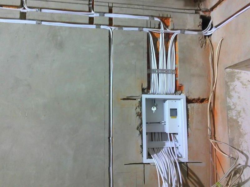
Proper cable management
The organization of the cable is as follows:
- Removing the flap cover and making holes in it for a corrugated pipe with a diameter of 16 to 20 mm.
- Corrugated pipe trimming before output.
- Removing the plug and the lead-in lead to the appropriate machine.
- Installing the cable on the bar with the eyes, fixing it with a plastic clamp. The screed is cut to the desired length with wire cutters.
- Marking wires with felt-tip pens.
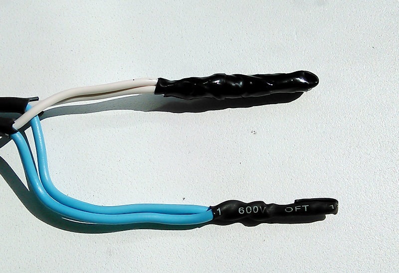
- Laying the wire in the heat shrink tube, lettering.
- Making notches on the plug for tight fixation in the holes.
- Placing the plug in the installation location and securing it with screws.
An alabaster should be used to secure the input cable in the strobe.
Wire cutting sequence
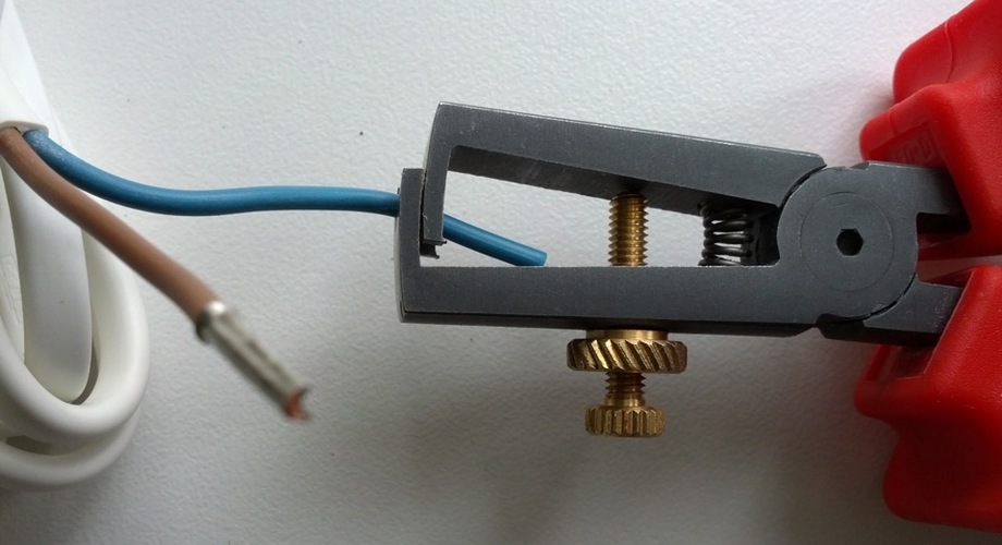
To remove the insulation, a special knife with a heel is used. Each core after removal of the insulating layer is marked. Further actions:
- Separate the wire from left to right above and to the right of the left corner below.
- Stripping the tip of the input cable.
- Winding wires 10 cm to the tip with masking tape.
- Cable marking.
It is necessary to leave a margin of conductor length 2 times the length from the fastener box to the entrance.
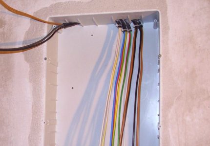
Ways to protect the inner filling of the shield
Internal parts are the most expensive part of the system. To prevent dust and debris from entering it, you can cover the ends of the wires with caps from pens, felt-tip pens or electrical tape. Movable elements are removed from the housing, and the cables are located inside without sharp bends. Laying scheme is implemented in the direction or counterclockwise, from left to right. Kinks are unacceptable.
At the end of the work, you will need to close the box with a cardboard cover or a complete cover and glue the gaps between the joints with paper tape.
Primary assembly of the electrical panel on the frame
To assemble the shield, a set of dielectric screwdrivers will be needed, among which there is a tool with a straight slot, a stripper, pliers, nippers and a hacksaw, a screwdriver and a tester. Modules are arranged in two ways:
- linear - at first, difavtomats and RCDs are placed, then circuit breakers;
- group - immediately there is an RCD or a difavtomat, then - machines, then the details are repeated.
Step-by-step assembly process on the frame:
- Modular units are mounted.
- Devices with the selected rating are installed.
- Combs are placed to connect the machines.
- Phase wires pop up.
- A neutral conductor is made.
- Earth is connected to a special bus.
- Devices with test buttons are placed.
After assembly, the shield is mounted on the wall. Before you turn off the box, you should check the quality of access to it.
Self-assembly of the electrical panel with knowledge of the circuit is not difficult. After finishing work, the box must be checked by turning off the machines and connecting the counter. Test phase, zero, and a single line.