At various firms manufacturing electrical products, the type designations on the contacts of the light switches may not match. You should understand what L means on the light switch and whether there are any other notation. This knowledge will help all interested parties, after purchasing the installation product, to correctly connect it to the existing power grid.
Connection Features
To understand the features of connecting a standard switch, you need to study the principle of its operation. As an example, convenient for description, a variety of devices with one key is selected.
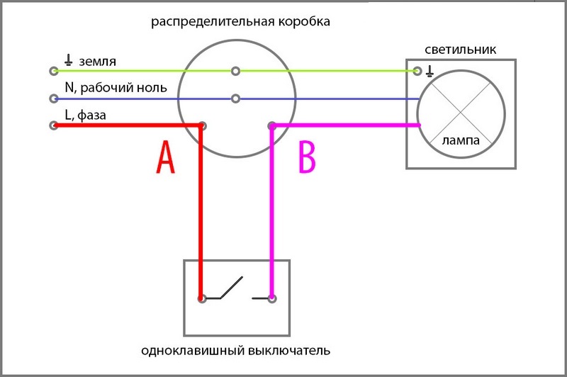
- the switch is always installed in the gap of the phase wire, the second end of which is diverted either to the junction box, or directly to the lamp;
- on both sides there are only two wires, each of them is intended for its own purposes;
- one of them is laid to the circuit breaker from the linear machine and is constantly energized;
- it is absent on the second wire, which is why the lighting device connected to the switch does not light.
Network 220 Volts come to it only after pressing a button or key when putting it into "On" mode. After that, a working lamp or bulb immediately lights up.
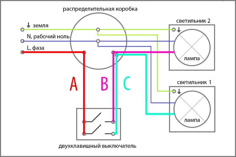
When connecting a three-key switch, the distribution of functions of each of the contacts is the same. But in this case, from the side of the conductors to the junction box or chandelier there are two contacts that serve for switching various groups of bulbs. Accordingly, the number of designations becomes large by one. The same is observed when using a three-key product, in which the number of contacts and lead-out conductors increases by another one. Knowing these features of the device switching device will help to decipher the marking L on the switch.
What stands for L
Conventional designations on light switches are applied to mark their contact connectors or to indicate the position in which their key is located.
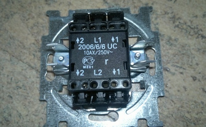
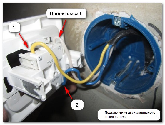
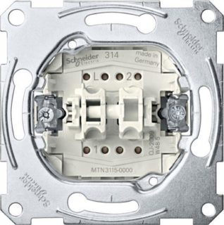
The contact to which the phase is supplied from the distribution panel is marked L on the switches for all types of devices - both single-key and multi-key.
Presumably, this symbol is taken from the first letter of the English word “Line”, meaning a line or a linear wire. The second contact also has its own designation, which is different for different manufacturers:
- The symbol L with the addition of a unit is L1.
- The same sign, but with the addition of a stroke - L`.
- Small arrow pointing up.
- Just a unit ("1").
For some manufacturers, this challenge is not indicated at all. If it is on top, a wire is led away from it to the chandelier or junction box.
The PUE stipulates on which sides the conductors to the circuit breaker should be connected and withdrawn. According to the requirements of standards, the connection is made from below, and the branch is mounted from above.
In two-key and three-key devices, the number of outlet conductors increases to two and three, respectively, which forces their manufacturers to mark additional contacts. Therefore, in their designations, such icons as L2, L3 or the same letter are often found, but with two or three strokes. It is also possible that instead of letters next to the output terminals there are only numbers corresponding to the number of the outlet conductor.
How output contacts are connected
 The presence of a large number of signs on the contacts of multi-key electrical switches causes certain difficulties with their connection. It is difficult for an inexperienced user without measuring equipment to determine which of the conductors is responsible for turning on a particular light bulb in a chandelier or one of the groups of illuminators. In this situation, you have to act by trial or error.
The procedure for each type of switch can be represented in the form of the following algorithm:
- in the single-key version, the switch has L and L1 - this means that only one outlet conductor is connected to the output;
- in a two-key analog, they will have to be connected to each of the output terminals one at a time, and watch which of the illuminators lights up;
- based on the experimental data, the necessary contacts are selected under the designations L1 and L2;
- in a three-key sample, the possibilities expand: you will have to sort through the connection order many times (the number of combinations of the three options is 6).
It is possible to simplify the last operation by connecting the "unidentified" lead-in conductors with the phase conductor one by one and observing which bulbs, groups or lamps light up.
Each time after connecting another wire and determining a group of illuminators, this tap is connected to a terminal selected specifically for the consumer under test. After that, the control function of this circuit is automatically transferred to the key, the switching mechanism of which is associated with this contact.
Designations on the case
In addition to the designation L, other symbols and icons are found on the switch of lighting devices at its working contacts or on the case.
Most often, manufacturers use the symbolic principle of marking two states of a switching device - on and off. Intuitively clear zero and one ("0" and "1") are traditionally used as such characters. The first of them corresponds to the state “Off” or OFF and is located in the lowest zone of the body of the electrical device. The second icon means “On” (ON) and is applied at the top. There are also such rare designations as arrows indicating the direction of switching.
Having familiarized themselves with what L is on the room lighting switch, everyone can independently connect it to the existing mains. In case of emergency, a faulty device can be repaired. This will also help the ability to understand the difference between the markings of different types of switches produced by different manufacturers.