In power circuits of 380 volts with high currents, according to the PUE, a converter of a special design, called a current transformer, is used. With its help, it is possible to reduce the value of the current indicator by the number of times specified by the technical characteristics. To understand the principle of operation of such converters, you will need to familiarize yourself with their design.
Design features
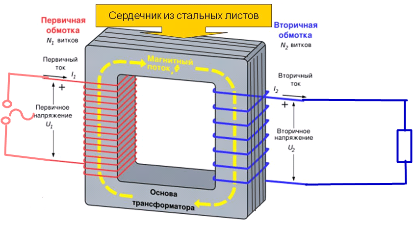
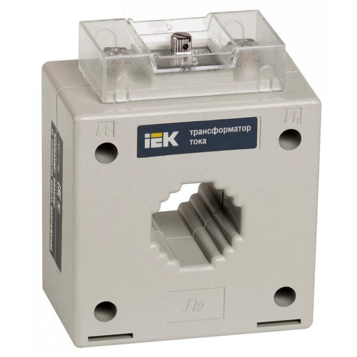
Electric current transformers contain the following structural elements:
- closed core (magnetic core);
- primary power winding;
- secondary (lowering) coil.
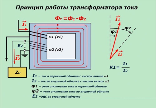
The primary winding is connected in series with the controlled circuit, so that all phase current flows through it. The secondary coil is loaded on a device connected to the network - a protective relay or a measuring device. Due to the difference in the number of turns in each of the coils, the current component in the secondary winding is reduced to a value determined by the transformation coefficient.
Since the resistance of the load circuits is negligible, it is believed that these devices operate in a mode very close to short circuit.
Usually they have several groups of secondary windings, each of which is used for its own purposes. They can connect to:
- protective devices (voltage relays, for example);
- metering and diagnostic equipment;
- control equipment.
The resistance of the output windings is strictly normalized, since even a slight deviation from the value specified in the TU leads to an increase in the measurement error or to a deterioration of the response characteristics.
A significant difference between CTs and their related voltage transformers is the functions performed by these devices and the principle of operation. Current transformers primarily provide protection for the connected load and the specified accuracy of the measurements. The second type is characterized by a purely converting mode of operation, which is relevant only for operation in power circuits.
Current Transformer Classification
 Understanding what the CT is intended for will help familiarization with the generally accepted classification of these devices. Known examples of converting devices differ in the following main features:
- Purpose - the function performed by each specific device.
- Installation method at the place of operation.
- Design features, including the total number of turns in the primary winding.
- Operating voltage and type of insulation of conductors.
- The number of stages of transformation.
According to the purpose, the known CT samples are divided into laboratory, protective, measuring and so-called "intermediate" devices.
The last category is intended either for connecting measuring instruments, or for equalizing current values in differential protection systems.
According to the installation method, the following types are distinguished:
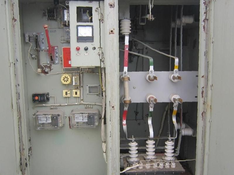
- for outdoor installation only (in switchgear cabinets);
- for indoor installation circuits (in indoor switchgear);
- converters built into electrical units and switching devices, which include generators and power transformers;
- overhead devices mounted on top of the structure (on bushings).
Portable samples are used for laboratory research, as well as for inspections and measurements.
According to the design of the primary winding, the current devices are divided into multi-turn, single-turn and bus models.In accordance with the operating voltage of the circuits in which these devices are installed, they are divided into transformers installed in networks of up to and more than 1000 volts.
By the type of insulating materials used in them, these products are divided into the following types:
- with "dry" insulation based on porcelain or epoxy;
- with paper-oil or capacitor protection;
- with compound filling.
By the number of available stages of transformation, all known devices installed in the power circuit are single-stage and two-stage (their other name is “cascade”).
Wiring diagrams
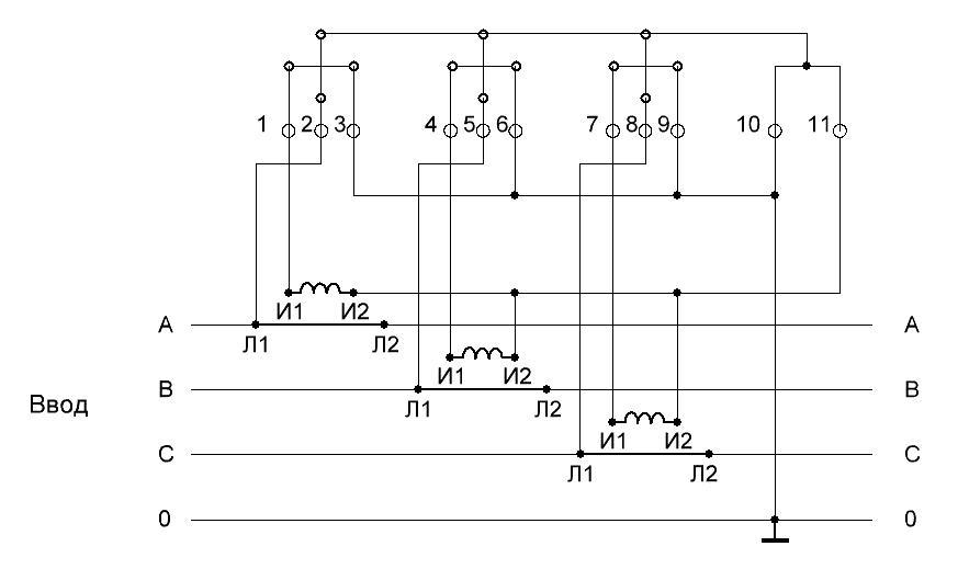
Various schemes for connecting current transformers mainly differ in the order of switching of the primary and secondary windings. The first of them is characterized by the simplest sequential inclusion (the so-called "tie-in") in the gap of the controlled phase bus. Another thing is the secondary circuit, consisting of several windings, which can be tripped according to the following schemes:
- “A full star, used to control the current parameters in each phase if necessary.
- "Star of incomplete type", used when there is no need to control all linear measuring circuits.
- Scheme of fixing currents of the "zero sequence", which includes a control relay.
On the outgoing feeders of 6-10 kV, in order to save, often not just three, but only two measuring transformers are installed (without one phase).
In this case, the secondary windings are turned on according to the incomplete star scheme. A common circuit called “zero-sequence current checking” is formed by connecting secondary windings to a full star. At the same time, the control relay used in it is included in the common wire break (“zero”). With exceptions of this type, the current passing through the winding is composed of all three phase vectors. If the loads are balanced, in case of single-phase or two-phase short circuits, a component arising from unbalance is allocated in the relay.
Main parameters and characteristics of current transformers
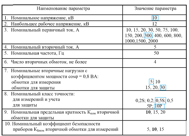
The technical parameters of any current transformer are described by the following main indicators:
- device class;
- Rated voltage;
- currents in the primary and secondary coils;
- transformation ratio of alternating current (as a ratio);
- permissible measurement error when connecting an electricity meter;
- permeability and cross section of the magnetic circuit (core);
- magnitude of the magnetic path.
The voltage rating in kilovolts is usually given in the passport applied to each specific device. Its operating value varies from 0.66 to 1150 kV. For more complete information about this and other indicators, you should consult the reference literature regarding the connection of transformers to electric meters.
 The value of the rated current in the primary coil is also learned from the accompanying technical documentation. Depending on the specific model of the converter, this parameter can range from 1.0 to 40 thousand amperes. The values of the current index in the secondary coil are usually selected 1.0 or 5.0 amperes (depending on the parameters of the primary circuit).
Sometimes, under the order, the manufacturer makes devices with secondary currents of 2.0 or 2.5 Amperes.
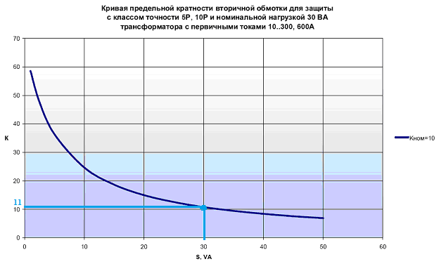
The transformation ratio (multiplicity) is an indicator of the proportion or ratio of the currents of the primary and secondary coils. The maximum ratio is understood as the ratio of the maximum primary current to its rated value, provided that the total error at a fixed secondary load does not exceed 10%. Nominal ultimate multiplicity means the same indicator at optimal load.This parameter characterizes the possibility of the normal functioning of protective devices in emergency conditions.
Current error
According to GOST 7746-89, there are three types of errors for CTs - current, angular and full. They are quantitative indicators of the deviations of the secondary current values, multiplied by the nominal coefficient, from the primary indicator.
The standard prescribes to calculate such errors only in the steady-state (with constant parameters) system operation mode and only if the shape of the primary current does not differ from the sinusoidal one.
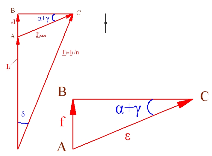
The current error mentioned in the description of multiplicities characterizes the relative difference between the effective values of currents, expressed as a percentage. Its angular equivalent is defined as the error between the vectors of two current components: the primary for the primary circuit and the first harmonic for the secondary. Based on these two values, the total error is calculated by summing them according to the formula given in the instructions.
The main purpose of measuring current transformers is to connect energy meters used to service three-phase power lines.