Any modern three-phase transformer is a special electrical device that provides consumers with electricity of the desired type and quality. Like any transformer converter, it contains primary and secondary windings, in which case there are three pairs. At high-voltage substations, thanks to this device, it is possible to obtain the voltage of the desired value, and then transfer it along the line with a grounded neutral.
Purpose and types
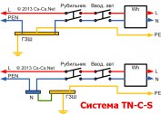
The classic station three-phase power transformer is used to convert high-voltage energy into a consumer-friendly form. High voltage (6.3-10 kilovolts) is supplied to its primary windings, and 220 volts more convenient for use in everyday life are obtained at the output. This value is measured between the phases and the zero-core transformer, called neutral. It is customary to designate it as phase voltage, in contrast to the linear 380 Volts counted between each of the phases.
Three-phase step-down transformers of this class provide current transmission from a local substation via an underground cable or power line directly to the end user. For these purposes, a special 4-core cable in an armored core or an SIP brand air wire is used. According to them, electric energy delivers directly to its destination - to the input and distribution devices of the served territories and objects.
According to their functional purpose, 3 phase transformers are divided into the following classes:
- linear (station) devices;
- special converting units.
Three-phase isolation transformers, used for decoupling electrical circuits and power circuits, are especially distinguished.
Special devices are divided into the following types:
- Test transformers. These include three-phase autotransformer systems.
- Devices used to power special equipment: welding units, in particular.
- Balancing transformer units.
The first two types are used for research purposes. Three-phase balancing transformers are used to eliminate phase imbalance that occurs in electrical networks due to uneven load distribution.
In electrical engineering, there are also variants of two-phase transformers, often used in electronic circuits and automation devices. They are arranged so that the two output voltages are shifted one relative to the other by 90 electrical degrees. Most often, such electrical solutions are used in welding equipment.
Transformer device
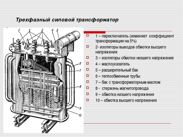
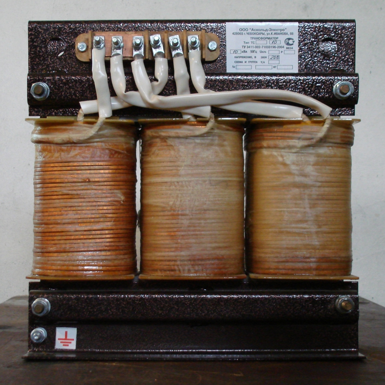
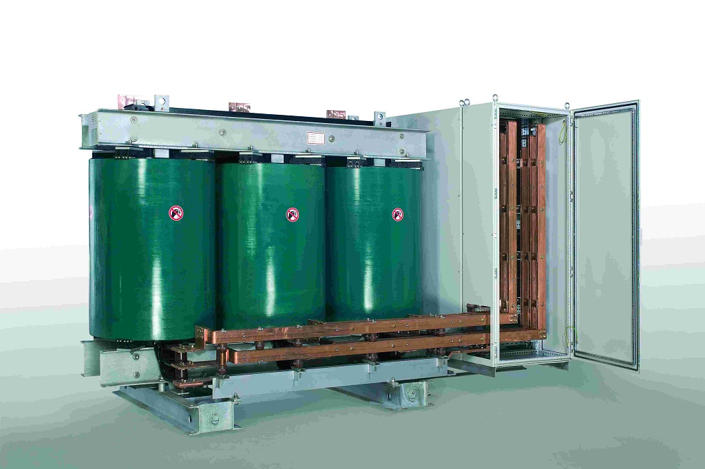
In their arrangement, three-phase transformers represent a prefabricated structure consisting of the following units:
- a base made in the form of a durable plastic frame;
- magnetic cores placed in frame sections;
- set of primary and secondary coils with wire windings;
- distribution (decoupling) panel with contact blocks;
- cooling system required to remove heat from the work area.
Each of the known versions of such devices in one form or another contains all designated nodes. At the same time, they differ in the way the windings are connected, as well as in the type of magnetic circuit used in them.The design features of individual models are reflected in their performance characteristics, in particular, on the magnitude of losses in the magnetic circuit and efficiency.
An exception is the transformer winding tap desoldering panel, due to which it is possible to combine connection groups to obtain the desired configuration.
Methods for connecting windings
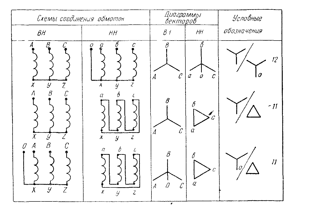
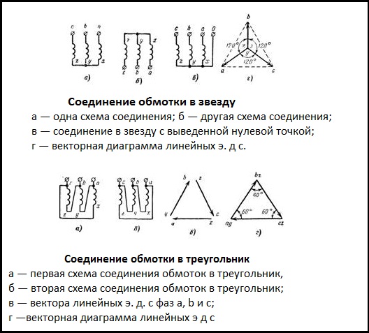
The main difference between various transformer circuits is the configurations used when turning them on (methods of connecting the windings). When organizing centralized energy supply, two classical schemes, called the "triangle" and the "star", are traditionally used. The first option involves the sequential inclusion of primary and secondary phase windings: the end of one coil is connected to the beginning of the next).
When using the "star" scheme, the beginnings of all phase conductors of the primary and secondary windings are combined at one point, called the neutral, and their ends are connected to a 3-wire load line. In this case, a cable containing four cores is required to transmit electricity. When connecting secondary transformer windings connected in a “triangle” to the line, only three conductors are used. Another option for their inclusion, which is called the "interconnected star." However, due to the rarity of its use, it is not considered.
Configuration options
When organizing power supply systems, several combinations of including the primary and secondary windings of a three-phase transformer are possible. The set of switching actions performed at the same time:
- The primary winding is performed as a "star", and the secondary - in the form of a "triangle".
- The second approach uses the reverse order of inclusion.
- In the third case, the already considered combination of the "star" - "star" type or the option with two triangles (another name - delta-delta) is used.
To take into account all the ways to turn on the primary and secondary windings and the subsequent calculation of the parameters of the transformer in electrical engineering, special identification tables are used. They provide possible combinations and combinations used if you want to connect the transformer to the line and get the most out of it. In each case, the efficiency of the entire energy supply system depends on the correct choice of this combination.
Parallel connection
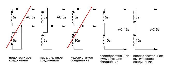
The parallel inclusion of the same secondary windings allows to increase the power (current) at the output of the device. This way it is possible to increase the efficiency and load capacity of the serviced line.
When using this approach, it will be necessary to take into account one important detail related to the order of connection of the secondary windings. To obtain the expected results, the windings must be switched in phase, which means connecting the same ends of all three coils at one point. If this rule is violated, the voltage at the output of two windings not connected in phase will be close to zero (the substitution principle applies). When this error is made when the transformer is turned on, its power and efficiency are significantly reduced. If during the secondary check it is found that the voltage has not changed compared to a single turn-on, then the coils are in-phase.
A conversion device, defined as a transformer 220 to 380 volts of 3 phases, can be obtained by using a special circuit with increasing output voltage. Its feature is the presence of one primary and three secondary windings included in the "star" or "triangle" pattern.