The brightness of the LED sources depends on the flowing current, and it, in turn, depends on the supply voltage. In conditions of load fluctuation, ripple of the lamps occurs. To prevent it, a special driver is used - a current stabilizer. In case of breakdowns, the element can be made independently.
Design and principle of operation
The stabilizer ensures the constancy of the operating current of LED diodes when it deviates from the norm. It prevents overheating and burnout of LEDs, maintains a constant flow during voltage drops or battery discharge.
The simplest device consists of a transformer, a rectifier bridge connected to resistors and capacitors. The action of the stabilizer is based on the following principles:
- current supply to the transformer and change of its maximum frequency to the mains frequency - 50 Hz;
- voltage regulation to increase and decrease, followed by equalization of the frequency to 30 Hz.
The process of conversion also involves rectifiers of high voltage type. They determine the polarity. Stabilization of electric current is carried out using capacitors. Resistors are used to reduce interference.
Varieties of current stabilizers
The LED lights up when the current threshold value is reached. For low-power devices, this figure is 20 mA, for super-bright - from 350 mA. The spread of the threshold voltage explains the presence of various types of stabilizers.
Resistor stabilizers
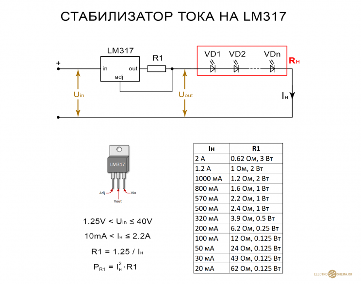
For an adjustable stabilizer of current parameters for low-power LEDs, the KREN scheme is used. It provides for the presence of elements KP142EN12 or LM317. The alignment process is carried out at a current strength of 1.5 A and a voltage of 40 V.
The LM317 node holds on the main resistor a constant voltage value, regulated by the trimming element. The main or current-distributing element can stabilize the current passed through it. For this reason, KEREN stabilizers are used to charge batteries.
The value of 8 mA does not change even with fluctuations in current and voltage at the input.
Transistor devices
The transistor regulator uses one or two elements. Despite the simplicity of the circuit during voltage fluctuations, there is not always a stable load current. With its increase on one transistor, the voltage of the resistor rises to 0.5-0.6 V. then the second transistor starts to work. At the time of its opening, the first element closes, and the strength and magnitude of the current passing through it decreases.
The second transistor must be bipolar.
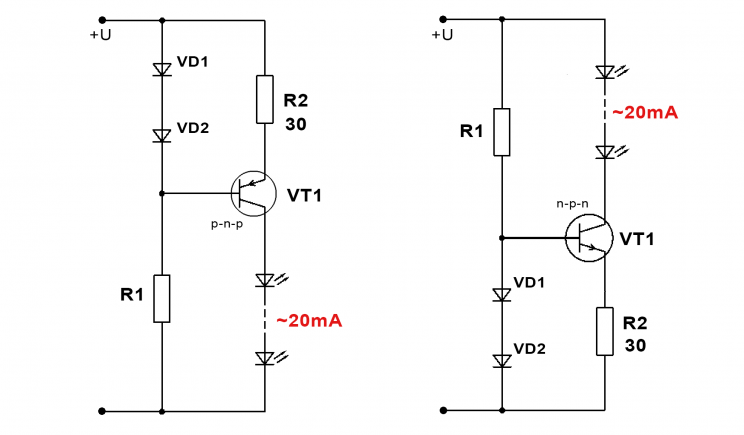
For implementation withcircuits with the replacement of zener diodes apply:
- diodes VD1 and VD2;
- resistor R1;
- resistor R2.
The current supply through the LED element is set by the resistor R2. To reach the linear section of the I – V characteristic, the resistor R1 is used with reference to the current of the base transistor. In order for the transistor to maintain stability, the supply voltage should not be less than the total voltage of the diodes + 2-2.5 V.
To obtain a current of 30 mA through 3 series-connected diodes with a voltage of 3.1 V in a straight line, 12 V is supplied.The resistor resistance should be 20 ohms with a dissipation power of 18 mW.
The circuit normalizes the operating mode of the elements, reduces current ripple.
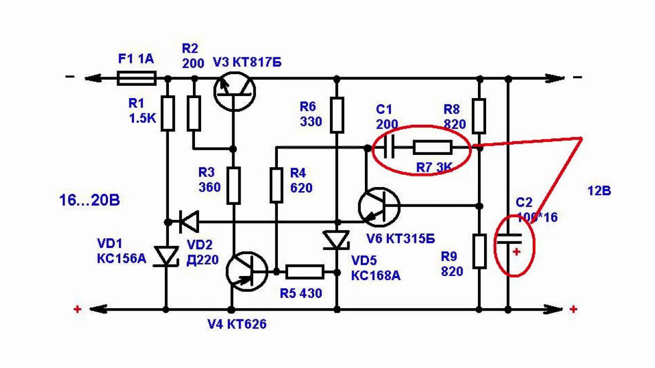
 Circuit with Soviet transistors. The permissible voltage of Soviet KT940 or KT969 is up to 300 V, which is suitable if the light source is a powerful SMD element. The current parameters are set by the resistor. The voltage of the zener diode is 5.1 V, and the power is 0.5 V.
The minus of the circuit is the voltage drop with increasing current strength. It can be eliminated by replacing the bipolar transistor with a MOSFET with low resistance parameters. A powerful diode is replaced by an IRF7210 element with 12 A or IRLML6402 with 3.7 A.
Field stabilizers
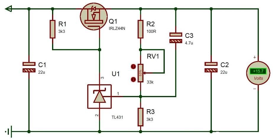
The field element is distinguished by a shorted source and gate, as well as an integrated channel. When using a polevik (IRLZ 24) with 3 pins, a voltage of 50 V is applied to the input, and 15.7 V is obtained at the output.
The earth potential is used to supply voltage. The output current parameters depend on the initial drain current, and are not tied to the source.
Line devices
The stabilizer or constant current divider accepts an unstable voltage. At the output, the linear device aligns it. It operates on the principle of constantly changing resistance parameters to equalize the output power.
The advantages of operation include the minimum number of parts, the absence of interference. The disadvantage is the low efficiency with a difference in power at the input and output.
Ferroresonance device
The stabilizer for alternating current of an outdated model, the circuit of which is represented by a capacitor and two coils - with an unsaturated and saturated core. A DC voltage is applied to the saturated (inductive) core, which is independent of the current parameters. This facilitates the selection of data for the second coil and the capacitive range of power supply stabilization.
The device works on the principle of a swing, which is immediately difficult to stop or swing harder. The supply of voltage occurs by inertia, therefore, a load drop or a break in the power circuit is possible.
Features of the current mirror circuit
A current mirror or reflector is built on a pair of matched transistors, i.e. with the same parameters. For their production, one LED semiconductor crystal is used.
Scheme of the current mirror according to the Ebers-Mall equation.The principle of operation is that the transistor bases are combined, and the emitters throw on one power bus. As a result, the parameters of the transient voltage of the base-transistor-emitter coupling are equal.
The advantages of the circuit are the equal stability range and the absence of voltage drop across the resistor-emitter. Parameters are easier to set using current. The disadvantage is the Earley effect - the binding of the output voltage to the collector and its oscillations.
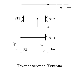 Wilson current mirror circuit.The current mirror can stabilize a constant value of the output current and is implemented as follows:
- Transistors No. 1 and No. 1 are included according to the principle of a standard current mirror.
- Transistor No. 3 fixes the collector potential of element No. 1 by twice the diode voltage drop parameter.
- It will be less than the supply voltage, which suppresses the Earley effect.
- The collector of transistor No. 1 is used to establish the circuit mode.
- The output current depends on transistor No. 2.
- Transistor No. 3 transforms the output current into an alternating voltage load.
Transistor No. 3 can not be coordinated with the rest.
Compensation Voltage Regulator
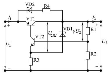
The rectifier operates on the principle of feedback circuit for voltage. Full or partial voltage equates to a support. As a result, the stabilizer generates error voltage parameters, eliminating brightness fluctuations for the LEDs. The device consists of the following elements:
- A control element or transistor that, together with the load resistance, forms a voltage divider. The emitter index of the transistor should exceed the load current by 1.2 times.
- Amplifier - controls the RE, performed on the basis of transistor No. 2. A low-power element is consistent with a powerful one according to the composite principle.
- Support voltage source - a parametric type stabilizer is used in the circuit. It equalizes the voltage of the zener diode and resistor.
- Additional sources.
- Capacitors - to smooth out pulsations, eliminate spurious excitation.
The compensation voltage stabilizers work on the principle of increasing the input voltage with a further increase in currents. Closing the first transistor increases the resistance and voltage of the collector-emitter zone. After applying the load, it is equalized to the nominal.
Chip Devices
For stabilizing devices, the 142EN5 or LM317 chip is used. It allows you to equalize the voltage, taking the signal from the sensor connected to the load current network via the feedback circuit.
It uses resistance as a sensor at which the regulator can maintain a constant voltage and load current. The sensor resistance will be less than the load resistance. The circuit is used for chargers, an LED lamp is also designed on it.
Pulse stabilizers
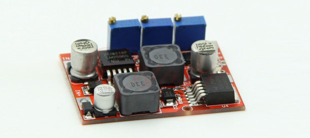
The pulse device is characterized by high efficiency and with minimal input voltage parameters create a high voltage of consumers. For assembly, the MAX 771 chip is used.
To regulate the current strength will be one or two converters. The rectifier divider aligns the magnetic field, lowering the permissible voltage frequency. To supply current to the winding, the LED element transmits a signal to transistors. The output stabilization is carried out by means of a secondary winding.
How to make a current stabilizer for LEDs yourself
Making a stabilizer for LEDs with your own hands is done in several ways. It is advisable for a beginner to work with simple schemes.
Driver Based
 You will need to choose a chip that is difficult to burn out - LM317. She will serve as a stabilizer. The second element is a variable resistor with a resistance of 0.5 kOhm with three leads and an adjustment knob.
Assembly is carried out according to the following algorithm:
- Solder the conductors to the middle and extreme terminal of the resistor.
- Put the multimeter in resistance mode.
- Measure the parameters of the resistor - they should be 500 Ohms.
- Check connections for continuity and reassemble the circuit.
The output will be a module with a power of 1.5 A. To increase the current up to 10 A, you can add a field worker.
Car Stabilizer
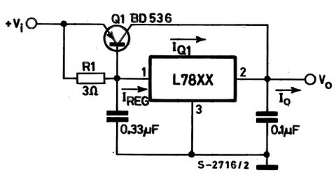
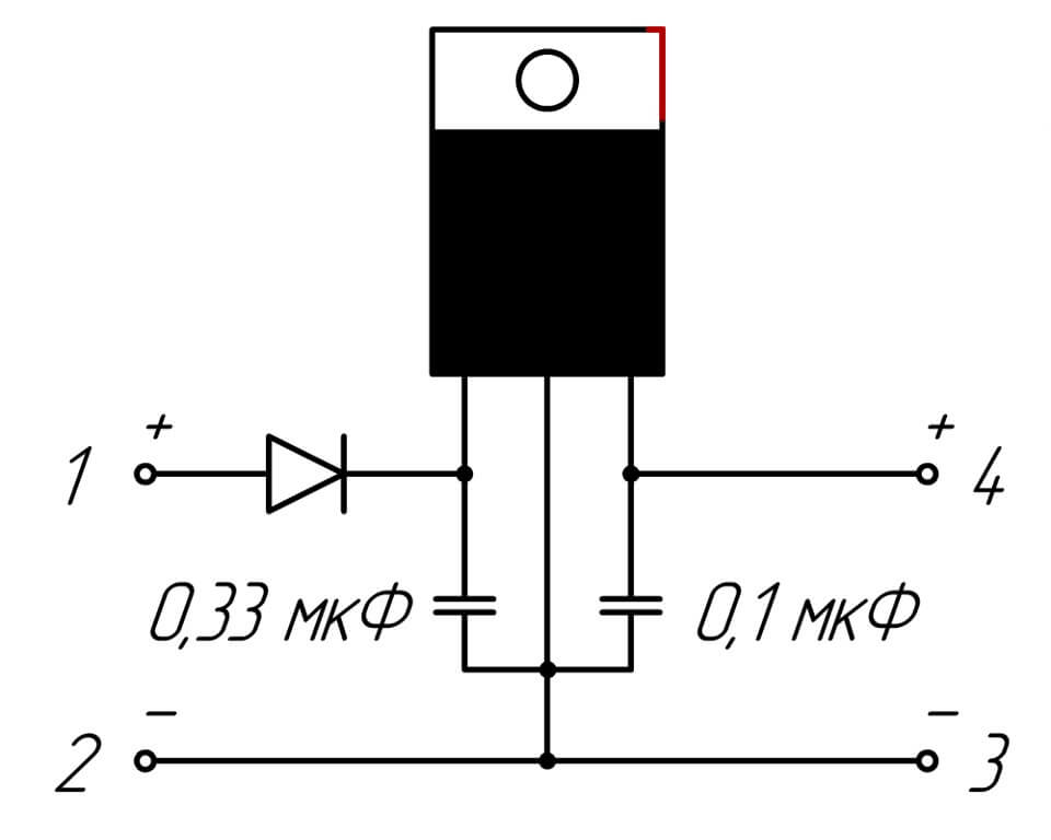
To work, you will need a linear device in the form of an L7812 chip, two terminals, a 100n capacitor (1-2 pcs.), Textolite material and a heat-shrink tube. Production is carried out step by step:
- The choice of the scheme for L7805 from a datasheet.
- Cut a piece of the right size from the PCB.
- Mark tracks by making notches with a screwdriver.
- Solder the elements so that the input is on the left and the output is on the right.
- Make the body out of the heat pipe.
The stabilizing device withstands up to 1.5 A load, mounted on a radiator.
The car body is used as a radiator by connecting the central output of the housing with a minus.
The nuances of calculating the current stabilizer
The stabilizer is calculated based on the stabilization voltage U and current (average) I. For example, the voltage of the input divider is 25 V, the output must be 9 V. Calculations include:
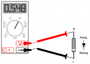
- Selection of the reference zener diode. Focus on stabilization voltage: D814V.
- Search for the average current I in the table. It is equal to 5 mA.
- Calculation of the supply voltage as the difference between the stable voltage of the input and output: UR1 = Uin - Uout, or 25-9 = 16 V.
- The division of the obtained value according to Ohm's law by the stabilization current according to the formula R1 = UR1 / Ist, or 16 / 0.005 = 3200 Ohms, or 3.2 kOhms. The value of the element will be 3.3 kOhm.
- Calculation of the maximum power by the formula PR1 = UR1 * Ist, or 16x0.005 = 0.08.
A zener diode current and an output current pass through the resistor, so its power should be 2 times greater (0.16 kW). Based on the table, this rating corresponds to 0.25 kW.
Self-assembly of the stabilizer for LED devices is possible only with knowledge of the circuit. Beginners are encouraged to use simple algorithms. You can calculate the element by power based on the formulas from the school physics course.