LEDs are used to transmit signals from remote controls, equipment, surveillance cameras, flashlights and lamps. They turn on in the forward direction, after the appearance of a positive voltage between the cathode and the anode. Therefore, in case of breakdowns, you can check the LED with a multimeter, establish the cause of the malfunction and eliminate it.
Verification Steps
Diodes operate at low DC voltage. It is generated by blocks to which it is problematic to connect. But part of the design of the LED is a semiconductor junction, due to which current is passed in a given direction. If there is enough current, the lamp lights up.
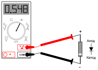
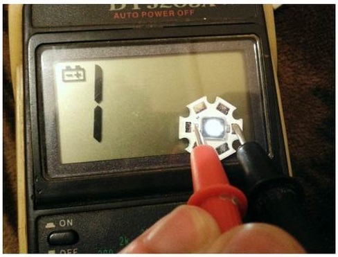
Using a multimeter, it is easy to determine the health of an element. To do this, the device is set to dialing mode, after which:
- The probes pop into the area of the semiconductor that needs to be checked.
- The red probe with a positive charge is connected to the LED anode.
- A black probe with a negative charge pops onto the cathode.
- The indicator of the voltage drop after the p-n transition should be displayed on the screen of the device.
- The polarity of the connection changes. In the absence of a voltage drop, the diode is operational.
If the multimeter does not have the “Ringing” mode, turn it with the switch to 1 Ohm.
LED Strip Testing Procedure
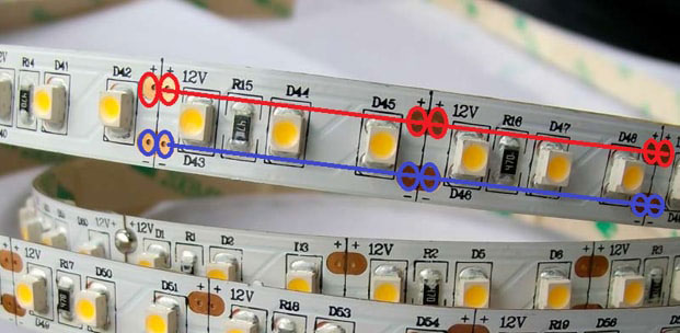
The LED strip is problematically checked by the multimeter, because it does not glow. Weak light occurs when testing in Hfe mode. Testing is also complicated by burnouts, not of the diodes themselves, but of contact tracks or current-carrying sections. To find out about a malfunction:
- Find the conditional identical segments of 3 LEDs along the boundary of the contacts and the transverse strip.
- Touch probes to each area in turn, applying current to the power contacts.
- Call the power supply - it fails due to a load drop.
A resistance test will provide a complete picture of the integrity of the LEDs.
Features of checking LED bulbs
Using a multimeter, you can ring color, standard and super-bright diodes.
Standard bulb with E27 socket
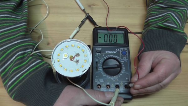
A similar lamp is used for household chandeliers or lamps. To check a working or non-working LED, you will need:
- Remove the diffuser from the light bulb using a plastic bank card placed between the element and the housing.
- Carefully slide the plastic card over the glue. A durable seam can be heated with a construction hairdryer.
- Open circuit board.
- Touch the elements with the probes and wait until they light up with a dim glow.
If the diodes do not light, the bulb is broken.
Superbright Diodes
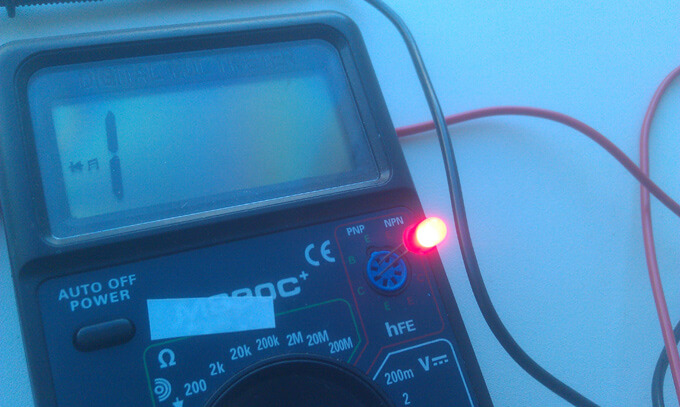
Blue, yellow or white LEDs are usually equipped with a garland. The test is conducted without probes using transistor sockets according to the following algorithm:
- Determine the pinout of the SMD.
- Find 8 sockets at the bottom of the device - 4 left for PNP transistors and 4 right for NPN transistors.
- Place the probes by inserting the anode into hole E and the cathode into hole C.
- Open the PNP element by applying a positive charge to the emitter E. A working LED will light.
- Change the polarity of transistors for NPN. The anode is placed on C, the cathode is on E.
Transistor sockets are convenient for testing diodes with long contacts without solder.
How to check the LED spotlight
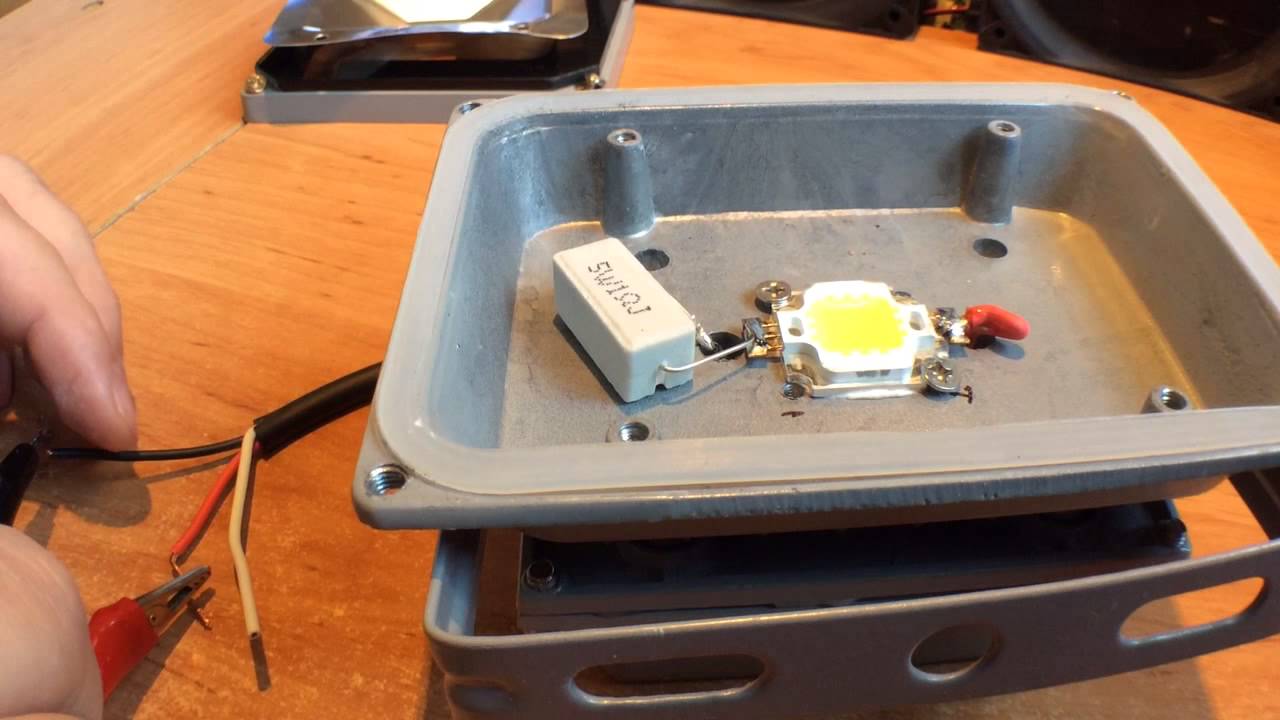
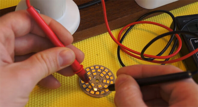
The LED is checked after determining the type of element. On the lights are installed:
- a board with small SMDs that are checked by dialing by analogy with a standard light bulb;
- a large yellow element operating on a voltage of 10-30 V.
The voltages of a large element are many for the tester, therefore, it is possible to determine the operability of an element only by the driver. It should correspond to the diode.
The nuances of testing infrared diodes
The infrared LED emits invisible radiation, so it is important to monitor the performance on the display of the multimeter. The probes are installed by applying a plus to the anode and a minus to the cathode. Touching the probes to the working IR diode, you can see the number 1000 on the screen. When the polarity is reversed, 1 is displayed.
For accurate verification of the infrared diode by the transistor sockets, a smartphone camera or digital device is used. The IR LED will need to be placed in the transistor slots and point the camera at it. About serviceability is indicated by a luminous blurry spot on the display of the gadget.
The soldering of the parallel red LED glow will clearly reflect the diode's performance. If at the moment of flickering a signal is supplied to the element, it should be replaced. If the backlight does not work, the remote control is faulty.
LED bridge test
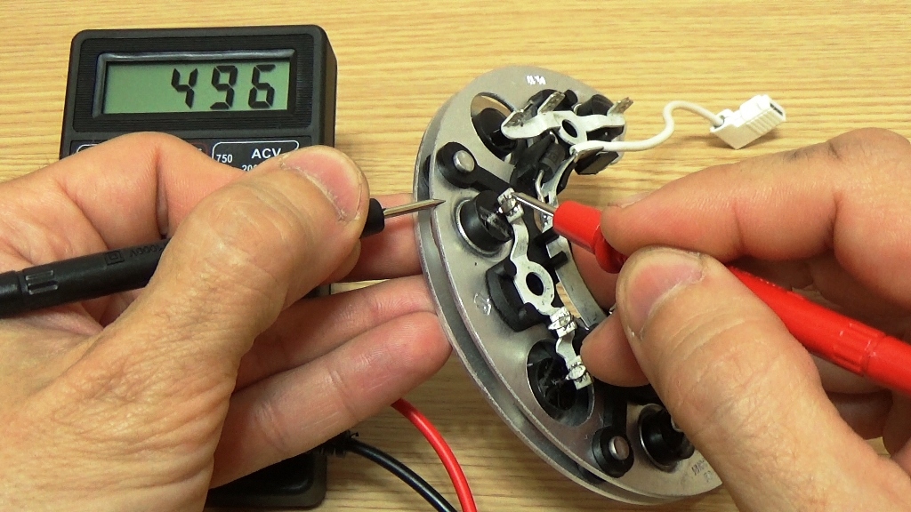
Diode bridge - assembly of 4 elements. They are connected so that the AC voltage is applied to two of the 4 pins, goes into a constant voltage DC and removed from 2 other pins. Zener diodes equalize voltage in a narrow range.
You can call the LED bridge like this:
- Find what pin to connect the multimeter to by conditional numbering.
- Ring the first diode, throwing the probes to pins 1 and 2.
- Test the second LED by connecting the probes to pins 2 and 3.
- Measure the parameters of the third diode by connecting the probes to pins 1 and 4.
- Determine the serviceability of the fourth element by throwing the probes on pins 4 and 3.
- View readings on the scoreboard.
The voltage stability is checked in the maximum range mode - 220 V. It is increased gradually and ceased to supply until the current flows through the circuit.
The black probe will need to be thrown to the anode, the red one to the cathode, and then the anode connected to the current limiting resistor, and the cathode to the power source.
The specificity of the dialing mode
A multimeter is a universal tester with which light-emitting diodes and other elements are checked. In the process, the device emits a squeak, or ringing, so the mode is called ringing.
The operation of the multimeter in the dial mode has several features:
- the switch is placed on the diode test, the probes pop up on the contacts;
- the polarity of the conclusions is determined, but if it could not be detected, the LED light source will not fail;
- with the correct connection of the probes to the contacts and the correct polarity, the working diode will light up;
- in the process of dialing, a current with a large value is not supplied, so the backlight of the diodes is visible only in a darkened room;
- in case of difficulties with dim lighting, they look at the instrument panel - the working SMD indicator is different from 1;
- High-power LEDs without soldering are tested after throwing adapters.
Before starting work in dialing mode, determine the anode and cathode of the light source under test.
LED test without soldering

You can check the LED-lamp without evaporating its diode elements. You will need an adapter, which is made independently from office paper clips, individual wire cores, pieces of needles for sewing, twisted pair wiring. The selected product is soldered to the probe probes.Between the parts of the adapter, a gasket is made of PCB, and then the whole structure is wrapped with an insulating tape.
The multimeter probes with an adapter are connected to the contacts of the light emitting diode or to the PNP pads. Testing is performed sequentially for each element.
Checking the operability of light emitting diodes in a flashlight
The standard flashlight test is a good example of work for which you do not need to solder the elements. To find out if LED sources are working, you need to:
- Disassemble the flashlight, remove the board with LEDs from it.
- Without removing the solder, place the probes on the pins of the PNP connector, observing the polarity.
- Put the switch on the bell.
- Look at the scoreboard and the backlight.
- Determine whether the circuit is working by checking its resistance. The resistance indicator, equal to zero, with a parallel connection indicates a malfunction of one LED.
Test each diode separately.
Available materials for verification
In addition to a multimeter, a lamp, a lamp or a searchlight on LEDs can be checked:
- Battery. The CR2032 battery is suitable for the computer motherboard. Its voltage of 3 V is enough for all types of diodes.
- 4.5 V and 9 V battery with ballast. It will give a voltage drop to a safe value. 750 Ohm is supplied to the Krona, from 150 to 200 Ohms to 4.5 V products.
- Battery from a radio call or remote control. The LED strip is tested with a 12 V element. Its contacts pop up at the poles, after which there are points with the LEDs blown out. Similarly tested connectors.
- A special led tester based on finger batteries with parallel connection.
- An old charger, from which the plug to the telephone is removed and the contact is protected. The red wire will be a plus and go to the anode. Black is used as a minus and connected to the cathode. If there is enough voltage, the LED lights up.
Testing a UV diode is complicated by its sensitivity to high voltage. The nominal value of no more than 3.4-4 V.
Self-made probe
It is problematic to ring a small LED with a standard probe, so you can do it yourself for comfortable use of the multimeter. For this, several elements are used.
Sewing needle

You will need:
- cases from black and red handles for handles;
- plugs and cable;
- steel sewing needles 35-45 mm in length and 0.8-1 mm in diameter;
- copper wire trimmings (steam - 250-300 mm long and steam - 120-150 mm long);
- rosin or alcohol rosin.
The manufacturing process is carried out in stages:
- The wire is cut and tinned with solder.
- The needles are tinned with solder so that 8-10 mm remain to the sharp parts.
- Conductors 0.3-05 mm in diameter are attached next to the ears of the needles, and then are wound in turns to the tinned area.
- The winding is covered with solder.
 Making a stylus out of a needle
 - Tinned cable bends in half around a screwdriver. The free sections are fastened together in a pigtail. The resulting loop is bent at an angle.
- Conductors are attached to the needles with a soldering iron.
- Plaque is removed from all joints with alcohol.
- A thread is wound in the center of the needles until bulges appear. They will need to be coated with Moment glue and inserted into the tips of the handle cases, fixing as evenly as possible.
- After the glue is dried, an epoxy is poured into the cavities, which hardens for 24 hours.
- The ends of the probes are tinned and soldered to the plugs.
- Problem areas to protect the shell from friction are placed in a heat shrink tube.
- Flexible conductors are made of red and black copper wires 1 m long.
- Tips with needles connect with flexible conductors with a soldering iron. Pieces of pens are fastened together.
The optimum wire cross section is 1.3 mm2.
Plug
You will need:
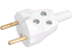
- Soviet plug from electrical appliances with brass pins;
- old probes from the multimeter;
- plastic tube;
- a wire with thick copper conductors;
- banana plugs.
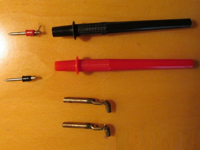
Progress:
- Removing the pins from the plug by unscrewing the top bolt.
- Removing the base from the old probes - the pins can be removed with pliers.
- File separation of the bent part of the pins with a file and turning them so that they are effortfully placed in a piece of plastic pipe.
- Separation and stripping of the speaker wire.
- Tinned cable ends and pin ends at solder points.
- Insert the wire into the base of the probes of the old multimeter and solder the brass plug to it.
- Pulling the cable back and fixing the area of its entry into the tube with heat shrink.
The second end of the wire is threaded into the connector. The cable for clamping strength will need to be clamped with a bolt.
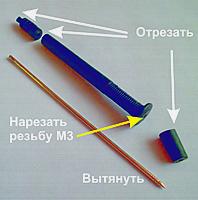
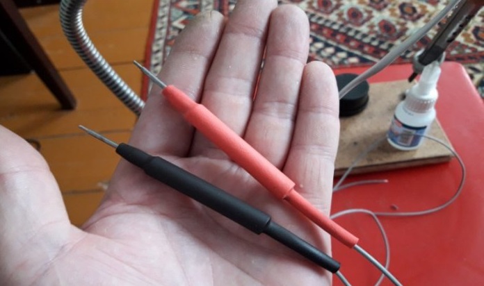
Laser CD drive pin
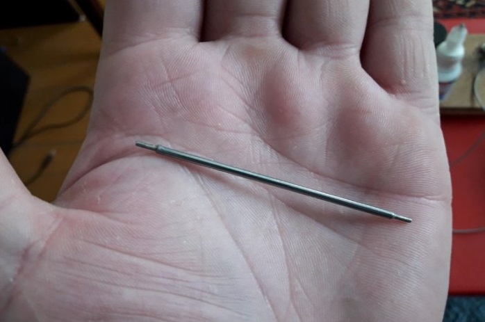
You will need:
- steel pin with sharp tips;
- shrink tubes of various sizes;
- two felt-tip pens (black and red);
- a tube according to the size of the pin;
- 300 V-rated copper wires
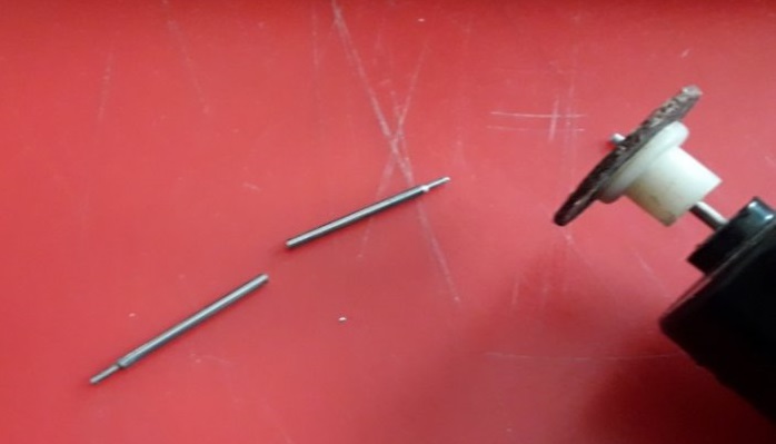
Probe manufacturing procedure:
- The hairpin is cut into 2 parts. Sawed edges are covered with flux.
- The ends of the wires are protected by 5 mm and tin coated.
- Wires with tinning are attached to the sawn sections - one for each.
- Thermotubes are put on and seated on the structure.
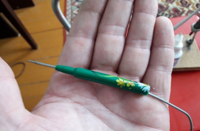
- Probe pens are made of felt-tip pens - it is enough to cut 5-7 cm from the beginning.
- Studs with soldered wires are inserted into the pieces of felt-tip pens so that the tips protrude from the felt-tip pen.
- Elements are fixed with epoxy.
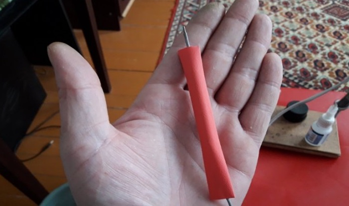
- After drying, the handle is installed in a color tube with heat shrink.
- The plugs are made from pieces of brass pipe from an antenna 3 cm long.
- A brass tube is inserted into the connector, a plastic one is fitted under it.
- The remaining ends are soldered to brass tubes and wrapped with electrical tape so that they fit the diameter of the plastic ones.
- Pieces of thermotube 4 cm long are put on the plugs and seated.
Epoxy can be replaced with “Secunda” glue with a pinch of soda.
Tips & Tricks
In the process of diagnosing LED devices, the following factors must be considered:
- if the voltage rating is at the limit, but the luminous flux does not appear, the current can be briefly increased;
- when high power is supplied, the LED source is heated;
- normal diode heating temperature - from 70 to 75 degrees (when touching, you can not burn your palm);
- using the battery, you can additionally set the resistance of the diode;
- when the polarity is changed, even a working element will not have a backlight;
- the best material for a home-made probe is nickel-plated needles that are quick and easy to solder;
- A working IR LED glows when directed to a sensitive area.
Checking LED light sources with the ability to work with a multimeter is easy. The user needs to prepare the conditions for testing - select the polarity, design probes or adapters, make special contacts.