Most of the options for connecting one device from another will not require the master to have complex skills such as self-laying additional wires or installing grounding in an apartment where there is none. However, in this case, the operation of the connected outlets is subject to some restrictions: you cannot connect certain types of electrical appliances to the network. To connect the outlet yourself, you need to understand the structure of the electrical wiring of the apartment and be able to identify the functions of the wires in the niche.
The device of an apartment or house electrical network
To figure out whether it is possible to draw a power outlet from the switch, you need to have a good idea of the structure of the home electrical network. An understanding of its device determines the possibilities of making modifications.
The main scheme of the apartment electrical network
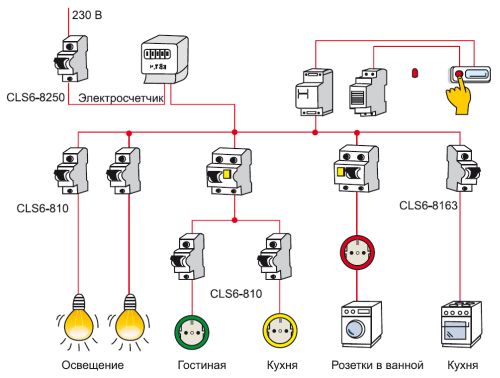
The apartment wiring path begins with an input board, which is powered by a cable coming from an external house electrical network. There is a panel device in the entrance of the house or at the entrance door of the apartment. Inside is a circuit breaker, which receives power from the cable. In Soviet-built houses, in which the power grid has not been updated for a long time, the function of the automatic device is performed by circuit breakers. Cables from the panel switch are sent to the electric meter and then to each of the machines serving the group. Groups do not communicate with each other, and their number is determined by how many loads are in the apartment. They can be distinguished by criteria such as ease of placement or type of load used. A strict rule is the separation of appliances located in residential premises, and those that are in the kitchen and bathroom, in different group bundles. From each of the machines, the cables are pulled into the distribution boxes (one or several), to which the apartment light switches and socket sockets are connected. This design optimizes power grid maintenance and disguises utility networks.
Connecting switches and sockets
To imagine how to properly connect the outlet to the switch or to the network, you need to remember the instructions from the Electrical Installation Rules. They establish that three cables with different functions are required for the process of plugging the outlet into the mains. To simplify the visual determination of the functions of the wires, they must differ from each other in the color of the insulating material (in practice, electricians sometimes ignore this rule).
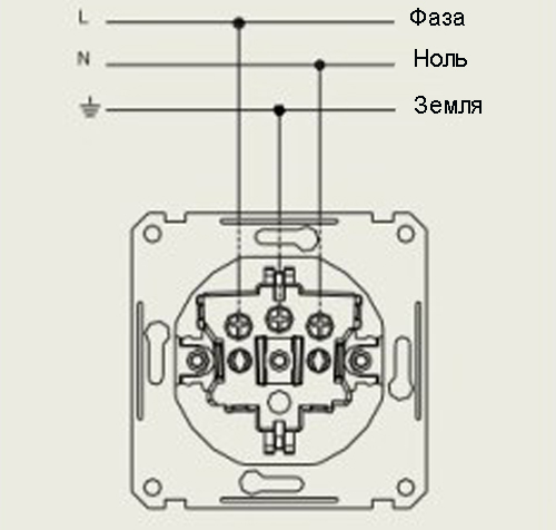
When connecting the socket, use the cables:
- Phase, the function of which is to power the served outlet, carrying electric current to it. This is the only wire whose insulation color is not regulated by the rules: the main thing is that it differs from the colors of the other two cables.
- The neutral wire is blue or blue. Like the phase, the junction box is connected to the power contacts of the socket.
- Grounding, the role of which is to protect residents from electric shock when touching the appliance body, as well as preventing short circuit situations. Its insulation material is yellow or green. The wiring is connected to special outlet pins reserved for grounding.
The practice of combining outlets with each other with a parallel connection to the network or serial. In the first embodiment, each of the combined elements retains independence.
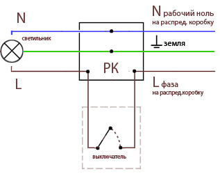
In the case of connecting the switch, only two cables are required, and both of them are phase cables. One put on the input of the connected device and connect to the phase of the group line. Another lead from the output of the light switch in the distribution box and is connected to the phase of the lighting device. The zero wire of the latter must be brought into the box, bypassing the switch, to the power cable.
Changing the purpose of an electric point and connecting one from another
Knowing the features of connecting rosette devices and lighting control boxes, you can replace one element with another or lay a connection between them. When performing any connection work, you must first disconnect this line, as well as the cables of adjacent lines, which you can inadvertently touch.
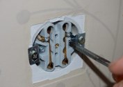
Replacing the outlet with a switch
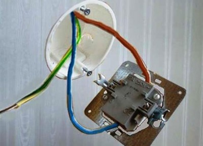
Of all the operations monitored, this procedure is most simple. After removing the old outlet, there is a trinity of cables - phase, zero and ground. Each element must be identified by the color of the protective winding. For reliability, you need to use a multimeter (it will be able to show the phase - the cable through which current flows when connected to the probes of the device), since during installation work, sometimes the color regulation of wires is ignored. In apartments of the old layout, where there was no modernization of the power supply network, instead of three conductors, there will most likely be two (phase and zero), since grounding was hardly used before.
Having determined which wire performs what function, you need to connect the phase component to the input of the switch, and zero to the output. Then work is carried out in the switchgear: zero, which was previously drawn to the socket housing, is turned off and then connected to the phase of the lamp. Grounding in the operation is not involved, regardless of whether it was used in the previous outlet or not. After that, the zero cable of the chandelier or sconce is connected to the network.
Replacing the switch with a power outlet
For the correct operation, the laying of additional cables is necessary. To connect the outlet, a triple of wires is required, and after removing the switch housing, only a couple of them remain. But to connect a power outlet to this place is quite allowed, and the socket will work, but during its operation it will be necessary to come to terms with some restrictions.
The refrigerator, electric kettles, heaters cannot be connected to the socket without grounding. It should also be taken into account when choosing the rated current that thinner wires are usually used for luminaires than for outlet designs.
First, make a switch on the site of the future localization of the outlet box. To its power contacts you need to connect the two wires remaining from the switch. One of them will have to be transformed from phase to zero: in the distribution box, turn off the cable that goes to the phase wire of the lamp before dismantling the lighting control device. It must be connected to the zero terminal of the group power cable.
Connection from switch socket
You can solve this problem in two ways: by simultaneously connecting two devices to one wire or by mounting a switch without manipulation in the junction box. Both options have advantages and limitations.
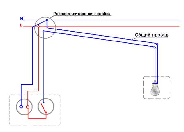
Connection of the switch from the socket without a distribution box
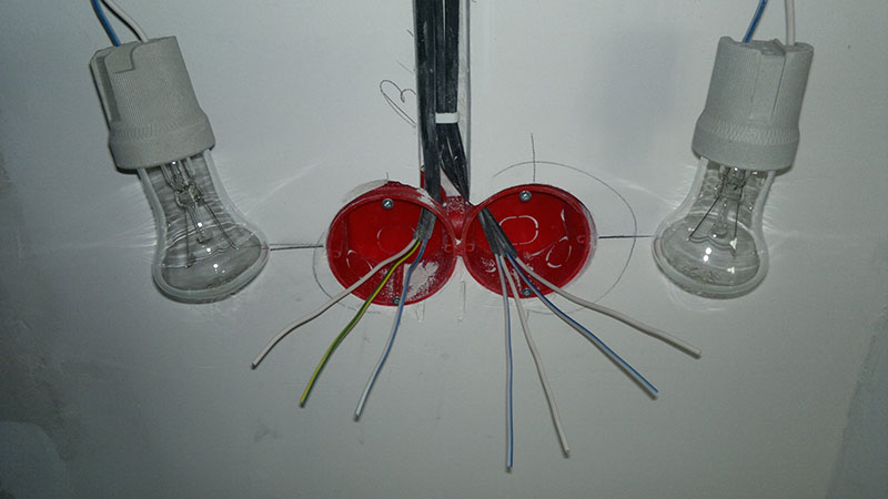
This scheme assumes that there are no additional twists between the distribution panel, the chandelier and the switch. A wire is sent from the shield - two-wire in the absence of grounding and three-wire in the presence of.It must be kept integral to the lighting device, and then it must be separated so that the zero remains there, and the phase goes to the switch. The phase from the switch button is brought up to the contact of the chandelier up the wall, and then along the ceiling.
If the chandelier has many light bulbs and there is an intention to connect it to a two-button switch, the shield wire is cut as described above, and a pair of cores from both buttons are led from the switch to the lamp. For this purpose, a cable with two cores is used. They are connected to the outgoing contacts of the switch (they will play the role of phases when the device is turned on) and guide the wire up to the chandelier. Again, the veins are divided into several centimeters and connected to the phase contacts of the chandelier.
This installation method has several advantages - it minimizes malfunctions due to ease of implementation and the absence of additional conductors, and is accessible even to an inexperienced master. The disadvantage of this type of connection is that when cutting the cable on disconnected cores, there is no insulating material. To avoid this, single-core conductors with high-quality insulation can be used. Then one independent cable from the shield bus is sent to the contact of the chandelier, another wire (phase) from the circuit breaker is led to the light control device, and from the last one the cable is laid to the chandelier (from one or two cores - according to the number of buttons).
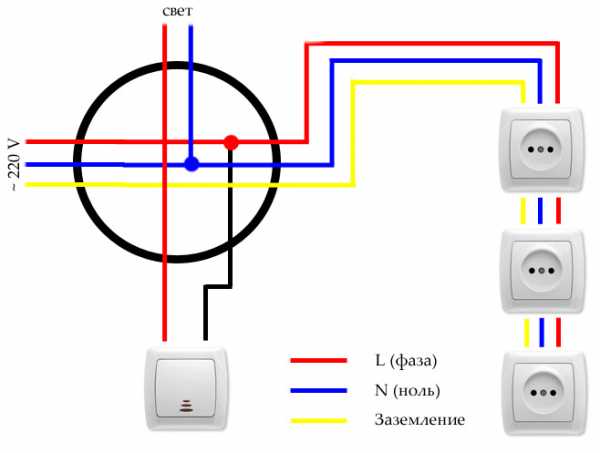
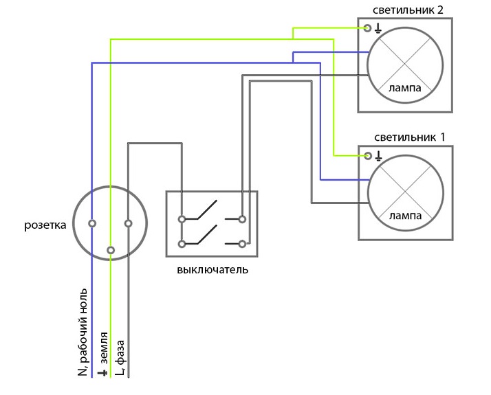
Connecting a switch and an outlet from one wire
To install the box with one button, first connect the apartment panel to the switch box with the help of a double (with phase and zero) wire. The lighting fixture is also connected to the distribution box by a twin-conductor. Then, a trinity of wires from the paired switch and the socket is introduced into it, while the path to the socket, and from the socket to the switch contact, must be laid from the phase clamp. The chandelier is connected to zero with one cable, the second with an unoccupied clip of the switch. If there is a grounding wire, it is connected in the junction box to the corresponding terminal.
To connect the two-gang switch, five cables are led from the box to the block of two devices. On the outlet they put zero and ground. A phase wire is supplied to the switch by means of a jumper in the switching unit. The two remaining cables are placed on the loose terminals of the switch. Conductors directing the phase and those that go to the light bulbs are twisted in the distribution box.
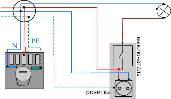
Connection from a power switch
This scheme is the most difficult to implement. Although it is not so difficult to connect a socket for temporary operation, additional cable routes must be laid to ensure high-quality operation of both elements of the unit. Therefore, the described connection can be implemented only as a last resort.
Two cables from the switch box are connected to the power contacts of the outlet. In this case, you must disconnect them from the switch so as not to create a short circuit situation. Since there is no cable for grounding, one of the wires coming from the switch must be turned to zero. This can be implemented in one of two ways:
- short-circuit the cables of the lighting device;
- switch off the cable coming from the push-button device in the switch box and connect to the group zero cable.
To realize a full connection of the outlet and the dimmer is very problematic. This operation requires the installation of conductors from the distribution box to the outlet.
How to connect the lamp through the switch from the outlet
Use conductors with three or four cores that perform different functions, and when separated, they are cleaned from insulation by several centimeters. Of course, the apartment must be previously de-energized.Wires and individual conductors are connected according to a pre-designed scheme, making sure that they stretch in straight straight lines and do not form knots or weaves. If installation is carried out in a room whose walls are made of wood, it is necessary to lay the paths in advance using plastic insulating plates. To lay the wiring paths hidden, you need strobes. Special channels are assigned for this option in reinforced concrete buildings.
When planning to replace the outlet with a light control device or to connect them with each other, it is advisable to first evaluate the restrictions imposed by the procedure corresponding to a specific task. Having made the decision to carry out installation work, you can purchase the necessary device with parameters that are suitable for the selected wiring diagram.