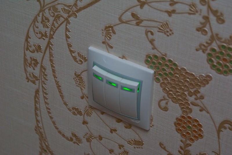
It is possible to create comfortable conditions from trifles, for example, a switch equipped with a backlight. This element has many advantages, provided that a suitable device is installed correctly.
What are the switches with indication of inclusion
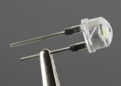
The backlight in electrical switches is a neon bulb or LED. Visually distinguishing them is almost impossible, the only difference is that neon lamps consume less electricity, but create a larger voltage drop. The minimum current for the LEDs is 2 mA, the voltage drop is 2 V, and for neon species, these indicators are 0.1 mA and 70 V, respectively. This is important to consider when choosing an electrical switch.
Switches with an indicator may not work correctly with different types of lamps. Uninterrupted and productive design works with halogen and incandescent lamps. It is better to abandon the operation of LED and energy-saving ones or take special measures. The most common malfunctions - the lamp blinks in the off position of the switch, the indicator in the switch does not light.
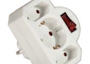
The backlight can be equipped with all types of switches and with any number of keys. The location of the glowing indicator can be different: at the top or in the middle of the key, in the center or at the bottom of the device itself.
Illuminated switch device
Connecting a switch equipped with indicator lights, as a rule, does not cause difficulties. It is enough to choose a high-quality model or to upgrade an already acquired one.
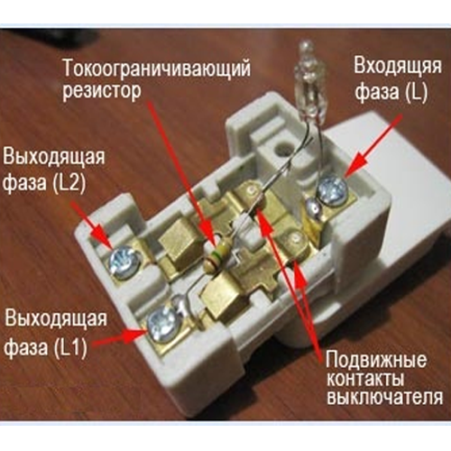
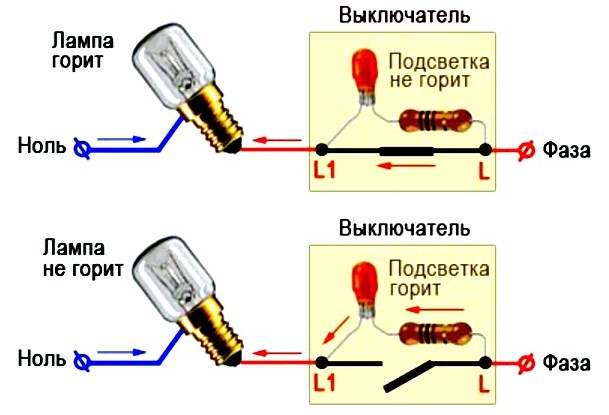
The backlight in the device is a series of neon lamps or resistance LEDs connected in series with each other. This small circuit is connected parallel to the switch contact. The circuit is always energized, regardless of whether the light is on or off.
If the switch is on, the backlight color is closed by a contact that is characterized by a lower voltage. The current practically does not flow through the backlight, therefore, it does not burn.
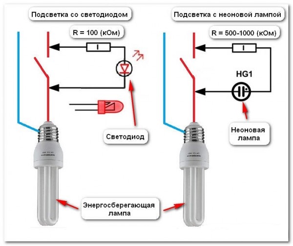
A current limiting resistor is connected in series with a neon lamp or LED in the switch. It is installed in order to reduce the current to optimal parameters. Different currents are required for LEDs and neon lamps, so resistors set different ratings.
- For neon bulbs - 0.5-1 megohms, power dissipation - 0.25 watts.
- For LEDs - 100-150 kOhm, the minimum power dissipation is 1 W.
Connecting directly through a resistor is not the best option. This is due to the performance of the circuit, as well as the tendency of the resistor to overheat. Also, it is possible that a reverse current will flow through the electric circuit. This will inevitably lead to a breakdown of the LED.
With diode
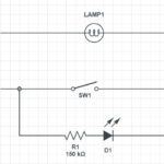
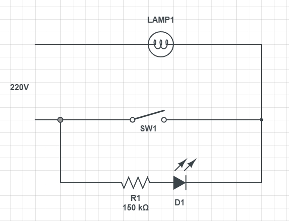
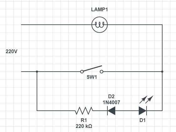
The first step is to solve the problem of reverse current flow. To fix it is simple - you need to install the diode parallel to the LED element.
If you connect the device according to a given scheme, the power dissipation of the resistor will not exceed 1 W, the resistance will fluctuate within 100-150 kOhm.
It is important to choose the right diode, which in its technical characteristics will be similar to the parameters of the LED bulb.
Such a scheme, despite the simplicity of implementation and performance, has a drawback - the backlight consumes a considerable amount of electricity, and the resistor heats up.
This type of backlit switch is compatible and will work correctly with incandescent lamps. If we talk about economical types and LED chandeliers, then the work will be observed intermittently.
To save power with a capacitor
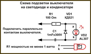
To eliminate the problem of overheating of the resistor, as well as reduce the amount of energy consumed, the circuit is additionally equipped with a capacitor. The parameters of the resistor also undergo changes, since its task is to limit the charge of the capacitor.
The value of the resistor will fluctuate within 100-500 AM, and the capacitor parameters - 1 mF, 300 V. The values of the resistor are established experimentally.
The advantage of such a scheme is that it practically does not consume electricity. Monthly consumption is about 50 watts. However, placing the capacitor in a very limited space is quite problematic. Also, the circuit does not guarantee uninterrupted operation with energy-saving and LED lamps.
How to connect a backlit switch
The principle of operation of the device is based on Ohm's laws. Electric current flows along the path of the smallest resistance with parallel connection of lines with different resistance.
The connection circuit has an equally high resistance, regardless of the type of indicator used - a neon bulb or LED. This indicator provides a limiting resistor.
When the switch is opened, the lamp serves as an ordinary conductor. A current flows through it with a small force, which is sufficient for the uninterrupted operation of the backlight.
Where to bring the wires
Before proceeding with the installation of a switch with an indicator, it is important to understand the design. To do this, it is recommended to remove the keys. Most often, they are fixed to the body using pins or latches.
Under the keys you can see the terminals for connecting wires. Almost always, they visually represent small copper pads with screws.
To connect the wires, their end must be removed from the insulating layer and strip the wire, hold it under the screw and contact plate, using the first to fix it securely. It should be tightened with effort, but the main thing is not to overdo it, the design is rather fragile. After a while, it is better to check the quality of the connection again and retighten again, since under the screw copper is slightly susceptible.
Connecting a light switch with one backlit key
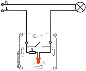
The connection diagram is extremely simple - zero is supplied directly from the dashboard to the lamp, and a phase is started at one of the switch terminals. From the second terminal, the wire is fed to the output of the lighting device.
Implementing this scheme is quick and easy. The number of terminals depends on the number of keys in the switch. On a single design there are only 2 terminals, and the socket should be equipped with two wires. It is simply impossible to get confused. It is required to run one wire under the terminal from the shield, and the second from the lighting device. Where and which does not matter.
How to connect a switch with two keys and a backlight
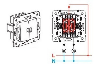
The connection diagram of this electrical design is not much different from the previous one. A three-wire wire is output to the undergrowth. Two cores are intended for a group of lighting devices, and one for supply. This is where all the differences end.
In the implementation, the method is a little more complicated, since you need to find a phase core and connect it to the required socket. The double switch is equipped with three contacts for connection.The phase is most often displayed in brown or red, and the color of the wires from the lighting device may be the same. Before connecting, the presence of phase voltage is checked, if necessary, the wire is marked.
How to turn off the LED in the switch
All the steps to dismantle a neon or LED lamp come down to replacing a conventional switch. The algorithm of actions is as follows:
- Completely de-energize the apartment, house, check the output voltage.
- Remove the decorative keys with a flat screwdriver or prying with fingers on both sides.
- Fixing bolts are unscrewed, the structure is removed from the mounting box.
- Using an indicator screwdriver, the contacts of the conductors are checked for voltage.
- When the connection diagram has been remembered, the wires are disconnected.
-
- Illuminated circuit breaker circuit
-
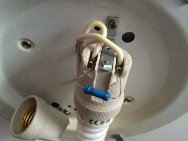
- Reworked circuit
The disassembled switch design is carefully inspected. It is equipped with latches that connect the two parts of the case. As soon as they are open, the switch will open. One part will be equipped with a resistor with an indicator light. The wires of the radio components gingerly bite from the backlight output and are removed. The switch is assembled and installed in the reverse order.
How to get rid of "blinking" lamps and possible problems
The main problem that owners of switches with indicators face is the flickering of the lamps and the indicator itself. Most of all, this phenomenon causes discomfort in the bedrooms and the study. Incorrect operation adversely affects the operating time of the switch and the lamp itself. You can get rid of the problem in the following ways:
- Give preference to LED lamps that are compatible with indicators in switches. Such lighting devices are already equipped with a soft start and a resistor. The device connects in a few seconds, so when the capacitor is discharging, it does not flicker. The main disadvantage is the high cost of such lamps.
- Parallel connection of the shunt resistor will help to get rid of the problem. It does not directly affect the operating mode, but a small current will still pass through the resistor. Its power should be 2 W, and resistance 50 kOhm.
- You can also connect an ordinary incandescent lamp with an energy-saving variety. In this case, the current flowing through the indicator circuit will pass through the filament. The disadvantage of this method is the large amount of electricity consumed.
- The cause of incorrect operation may be improper installation. For example, a mistake made may cause the switch to cut off zero, not phase. This can cause not only incorrect operation, but also a circuit. To solve the problem, it is enough to correctly connect the switch or call the electricians.
The easiest, but not the most convenient way to get rid of the problem is to remove the backlight from the switch or install the usual modification, not equipped with light bulbs.