High-quality uniform lighting can be created using different light sources. Energy-saving fluorescent lamps are actively installed in homes, offices, and factories. Their installation and circuitry is more complicated than that of incandescent bulbs. For proper installation, the master must know how the device functions, what types are and what circuit to use for connection.
Lamp device
A fluorescent counting source is a lighting device in which ultraviolet radiation is converted into visible light of a certain spectrum. The glow is achieved due to the electrical discharge that occurs when electricity is supplied in a gas environment. Ultraviolet is formed, which acts on the phosphor. As a result, the light comes on and starts to shine.
Most fluorescent tubes are made in the form of cylindrical tubes. More complex geometric shapes of the flask may occur. Along the edges of the tube are tungsten electrodes that are soldered to the outer pins. It is to them that voltage is applied.
The flask is filled with a mixture of inert gases with negative resistance and mercury vapor.
The standard light bulb circuit consists of a starter and an inductor. Additionally, various control mechanisms can be used. The main task of the inductor is to generate a pulse of the required magnitude, which can turn on the lamp. The starter is a glow discharge, in which the electrodes are in an inert atmosphere of gases. A prerequisite is that one electrode must be a bimetallic plate. If the lamp is off, the electrodes are open. When voltage is applied, they close.
Classification is carried out according to different criteria. The main one is light. It can be daytime or white with different color temperatures. Separation is also made according to the width of the tube. The larger it is, the higher the lamp power and the area of the illuminated area. Fluorescent lamps are divided by the number of contacts, operating voltage, the presence of a starter, shape.
Principle of operation
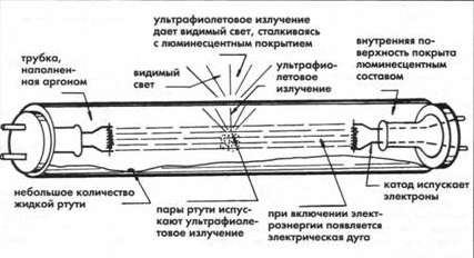
Supply voltage is applied. At the initial moment, electric current does not flow, since the medium has a high resistance. The current moves in spirals, heats them and is fed to the starter. A glow discharge appears. After heating the contacts, the bimetallic plates close. The temperature on the bimetallic part drops and the contact in the network opens. This leads to the fact that the inductor creates the necessary impulse as a result of self-induction, and the lamp begins to shine. Arc discharge is supported by thermionic emission occurring on the cathode surface. Electrons are heated by the action of the current, the value of which limits the ballast.
The light appears due to the fact that a special substance is applied to the lamp - a phosphor. It absorbs ultraviolet radiation and gives a glow of a certain range. The color can be changed by applying phosphors of various compositions to the flask. They can be from calcium halophosphate, calcium-zinc orthophosphate.
The main advantages of the lamp are energy saving, long life, bright glow. Among the shortcomings, the impossibility of a direct connection to the network and the presence of mercury inside the bulb can be highlighted. Lamps are more expensive than incandescent bulbs, but cheaper than LED light sources.
Connection Methods
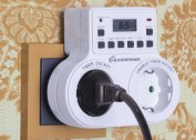
There are various options for connecting a fluorescent lamp to the network.The most popular luminescent luminaire circuit is an electromagnetic ballast connection.
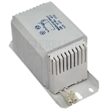
The scheme with electromagnetic ballast (EmPRA)
The principle of operation of this circuit is based on the fact that when a voltage is applied in the starter, a discharge occurs, leading to the closure of bimetallic electrodes. The electric current in the circuit is limited by internal throttle resistance. This leads to the fact that the operating current increases almost 3 times, the electrodes heat up sharply, and after a decrease in temperature, self-induction occurs, leading to ignition of the starter fluorescent lamp.
Cons of the scheme of a fluorescent lamp with EMPR:
- High energy costs compared to other methods.
- Long startup time - approximately 1-3 seconds. The higher the wear of the light bulb, the longer it will light up.
- Does not work at low temperatures. This makes it impossible to use in a basement or garage that are not heated.
- Stroboscopic effect. Flickering negatively affects human vision and the psyche, so such lighting is not recommended for use in production.
- Buzz at work.
The circuit provides one choke for two bulbs. Its inductance is enough for both light sources. Starter voltage - 127 V, for a luminaire with one lamp, a voltage of 220 V.
There is a scheme for a 220 V fluorescent lamp with a throttle-free connection. It lacks a starter. Such a non-starter connection is used when the bulb burns out. The design also has a transformer and capacitor to limit the current. For lamps with a blown filament, there are alterations to the circuit without a transformer. This makes the construction easier.
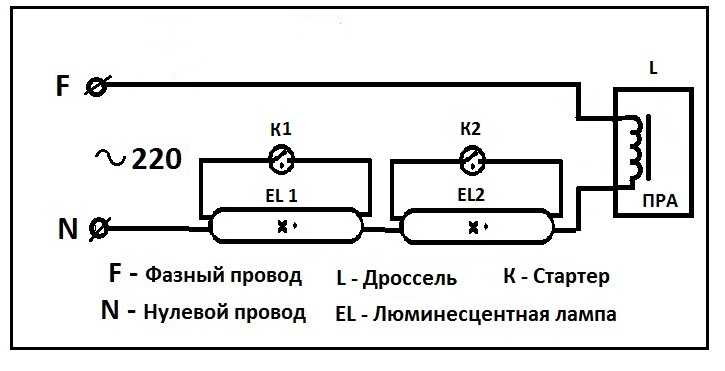
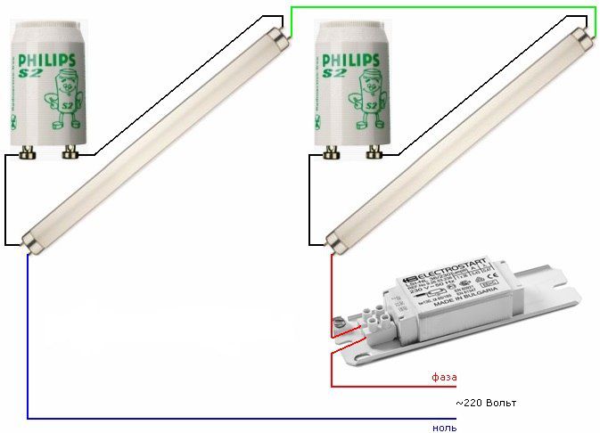
Two chokes and two tubes
This method applies to two lamps. You need to connect elements in series:
- Phase - at the input of the throttle.
- From the output of the inductor, connect one contact to the first lamp, the second to the first starter.
- From the first starter, the wires go to the second pair of contacts of the first lamp, the free wire must be connected to zero.
The second lamp is connected in the same way.
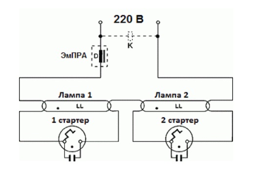
Connection of two lamps from one choke
This option is used infrequently, but it is easy to implement it. The dual-tube serial connection is economical. For implementation, an induction inductor and a pair of starters are required.
Scheme of connecting fluorescent lamps from one inductor:
- A starter is connected in parallel to the lamp pin output.
- Free contacts are connected to the mains via a choke.
- In parallel with the light sources, capacitors are connected.
Budget switches may periodically stick due to increased starting currents. In this case, it is recommended to use high-quality switching devices. This will ensure a long and stable operation of the fluorescent lamp.
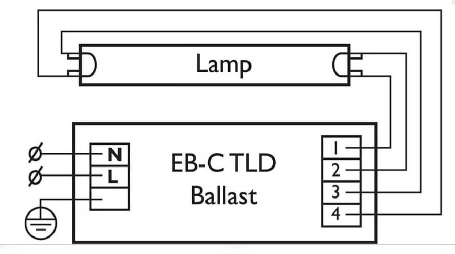
Electronic ballast circuit
All the disadvantages of EMPA led to the fact that I had to look for another way to connect. As a result, the electromagnetic ballast was replaced by an electronic one, operating not at a network frequency of 59 Hz, but at a high 20-60 kHz. Thanks to this decision, the blinking of light is excluded. Such schemes are used in production.
Visually, the ballast is a block with terminals. Inside there is a printed circuit board on which the electronic circuit is assembled. An important advantage of electronic ballast is its miniature size. You can even place the unit in a small light source. Also, the startup time is shorter, and the device works silently. The method with electronic ballast is also called non-start.
Assembling a circuit of such a device is not difficult. Usually it is located on the back of the device.The diagram indicates the number of light bulbs for connection, all explanatory labels, information on technical characteristics.
How to connect a fluorescent lamp:
- Contacts 1 and 2 - to a pair of contacts from the lamp.
- Contacts 3 and 4 - for the remaining pair.
It is necessary to supply power to the input.
Circuit with voltage multipliers
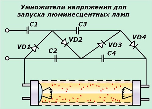 To increase the validity period, a method without electromagnetic ballast can be used. The operating time is extended provided that the lamp power does not exceed 40 watts. The filaments can be blown - they should be short-circuited in any situation.
Such a circuit allows you to rectify the voltage and increase it twice. The lamp lights up immediately. To implement the circuit, you need to choose the right capacitors. 1 and 2 are selected at 600 V, 3 and 4 - at 1000 V. The disadvantage is the large size of the capacitors.
Connection without starter
The starter causes additional heat in the fluorescent lamp. He also often fails, which is why this part has to be replaced. There are circuits in which a fluorescent light source works without a starter. The electrodes are heated to the desired level using transformer windings, which act as ballast.
When buying a bulb, you need to pay attention to the inscription RS - quick start. It is these products that work without a starter.
Scheme with serial connection of two lamps
There are two lamps that need to be connected using one ballast in a sequential manner. To perform such work, the following components will be required:
- Induction choke.
- Two starters.
- Two luminescent lamps.
The connection diagram of the fluorescent lamp is as follows:
- A starter is connected to each lamp in parallel to the pin input at the end of the bulb.
- The remaining contacts should be connected to the mains through a choke.
- Capacitors are connected to the contacts of the bulbs. They are necessary in order to reduce the intensity of interference and reactive power.
Capacitors are selected taking into account the load.
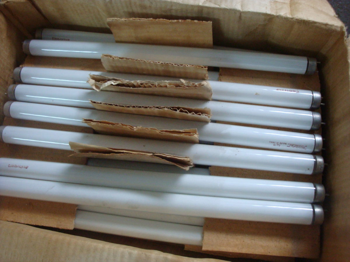
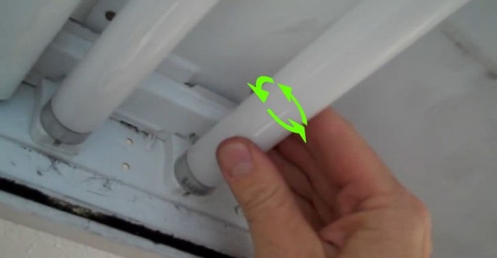
Replacing Fluorescent Tubes
The luminescent light source differs from classical halogen lamps and products with a filament for a long service life. But even such reliable bulbs can fail, which is why they have to be replaced.
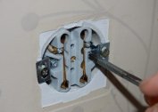
Replace as follows:
- Disassemble the lamp. It is important to carefully remove all parts so that the device is not damaged. The fluorescent tubes must be rotated around the axis in the marked direction. It is indicated on the holder by arrows.
- After turning 90 degrees, the handset should be lowered. Then the contacts will easily come out of the corresponding hole.
- Visually inspect the integrity of the light bulb, filament. If there are no visual problems, damage may be caused by internal components.
- A new light source should be taken. Its contacts should be in an upright position and placed in the hole. After installing the bulb, you need to scroll it in the opposite position.
Remove the device carefully so as not to break the glass flask. Inside is mercury, which is hazardous to health.
After the system is assembled, it is possible to supply power, turn on and start testing. The final step will be to install a protective cover on the lamp.
Health Check
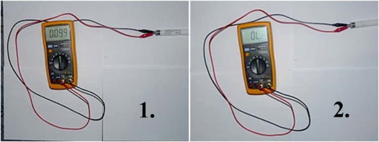
You can check the assembled system using a tester that checks the filament. Its allowable resistance should be 10 ohms.
If the test device shows infinite resistance, the bulb is only suitable for use in cold start mode. Also, infinity can be shown in case of a malfunction of the light source.The normal resistance that the tester should show reaches several hundred ohms. This is due to the fact that in the normal state, the starter contacts are open. In this case, the capacitor does not pass direct current.
If you touch the throttle terminals of the multimeter with the probes, the resistance will gradually drop to a constant value of several tens of Ohms.
The exact value cannot be determined using a conventional tester. But on some devices there is a function of measuring inductance. Then, according to the EMPR data, one can check the values. If they do not match, you can judge the problems with the device.