The time relay is an electrical device designed to turn devices on and off with a time delay. Equipment of this class is widely used in industrial plants, providing an optimal mode of operation and control without human assistance. In addition, a time switch is often used in everyday life: when watering work in the country, for example, or with the aim of timely turning off the lighting.
Types and classification
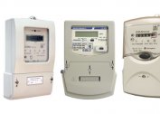
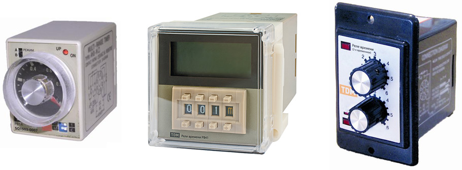
According to the installation method, the known images of the time relay are divided into the following types:
- block type devices;
- switches embedded in an electronic circuit;
- modular devices.
Samples of the first type are installed directly in switched circuits, and their power buses are connected directly to phase and zero. Sometimes a distribution box is used for this.
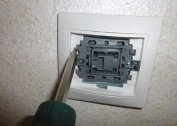
Built-in relays do not need a separate power supply, as they are part of more complex electronic circuits.
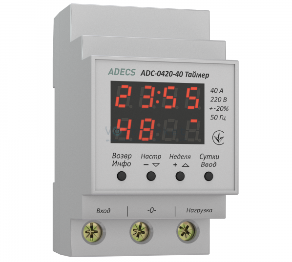
The modular devices are mounted on a DIN rail in the control cabinet and connected to the zero and phase buses displayed here.
According to the principle of their action, time relays have the following versions:
- electromagnetic type;
- pneumatic and mechanical devices;
- electronic relays.
In everyday life, electronic and electromagnetic devices are most often used, which is explained by the efficiency of their work and accessibility.
Advantages and disadvantages of the device
The advantages of electronic products are manifested in their high reliability and functionality. Among the disadvantages are the limited intervals for which you can configure the relay during programming, as well as the high cost in comparison with electromagnetic samples.
The main advantages of electronic devices are:
- relatively low cost in combination with a wide range of settings - the ability to set daily intervals;
- simplicity of design in comparison with electronic models;
- lack of need for programming and correction of time relay settings to turn on the light or power equipment.
The disadvantages of these devices include a limited service life, as well as some difficulties with installation and use in DC circuits.
Device and principle of operation
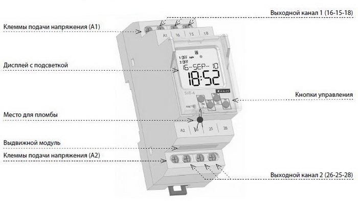
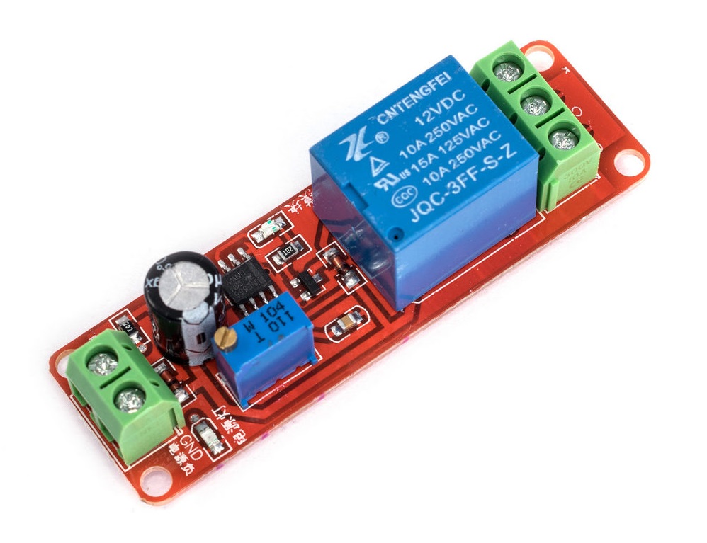
The principle of operation of a classic time relay is easiest to understand after familiarizing yourself with its device. Any such product contains the following required components:
- module for setting the response time (timer);
- setting body displayed on the front panel;
- an actuator triggered after a predetermined time.
The principle of operation can be represented as a sequence of simple operations:
- As soon as the relay is programmed for a certain period of time, its internal mechanism starts to work in the countdown mode.
- After a specified interval, the Executive unit turns on or off the lighting network - supplies or removes power from it.
If a relay is used to control the operation of an electric motor, its operation is based on the same principle. Only the executive elements are not his own contacts, but the powerful contactors of the magnetic starter.
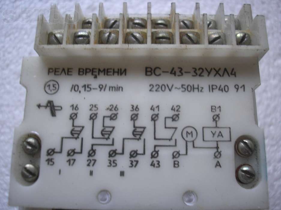
How to read markings
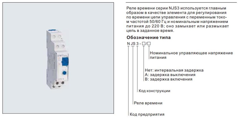
When choosing a marking code, manufacturers tried to simplify its perception as much as possible.Only the most necessary data is indicated on the relay case:
- manufacturing firm;
- device model
- rated voltage (usually 220 volts).
When marking, the type of current at which the given brand of the device is operated is sometimes indicated: constant or variable.
The housing may provide data on the maximum permissible current load. Most time relay samples also mark input and output contacts with a separate designation of “zero” and “phase”. Among the well-known manufacturers of these products, the Russian companies Meander, as well as Relay-Automation and Novatek-Electro, stand out especially.
Schemes of connection of a timer
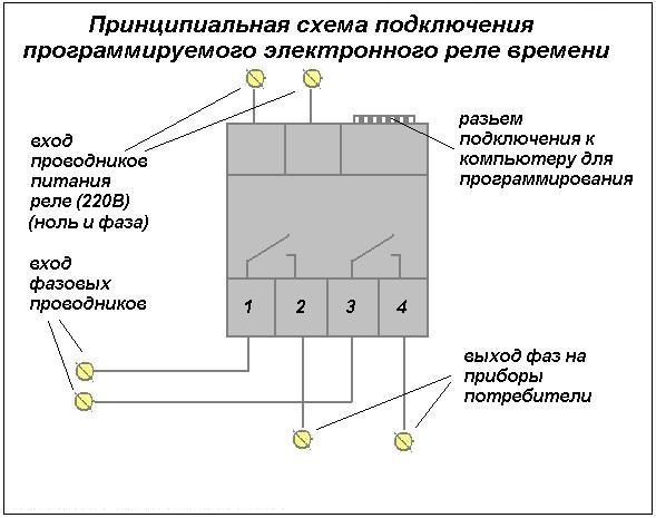 A variety of circuits are used to connect the time relay. Their choice depends on what load is supposed to be switched with its help. The connection diagram of the simplest type time relay is selected so that it ensures the stable operation of this device. The only drawback is that with their help it is possible to switch only one line with a limited load. Such consumers may be street light sources (lights) or mechanisms for watering the lawn.
Another circuit is used to control significant current loads. In this case, the contactor of the starter connected to the three-phase power circuit of the induction motor, for example, is controlled from the time relay. There are other options for installing and turning on the device, depending on specific operating conditions.
Step-by-step installation instructions
 Before trying to independently connect a time relay to a controlled circuit, you will need to determine the type of power supply - single-phase or three-phase. It is also necessary to know what load the device will switch, and at what time intervals it should be designed. Based on these data, a relay is acquired with characteristics suitable for the stated purposes. Further steps to install it are as follows:
- By means of an introductory machine, the mains to which the time relay is planned to be connected is de-energized.
- The product is fixed on a DIN rail in a cabinet next to the meter.
- On the relay case there are input and output contacts marked according to generally accepted marking.
- The phase and zero going from the counter are connected to the input terminals, and the conductors extending towards the RCD or the machine are connected to the output terminals.
Experts advise to test it for operability even before turning off the electricity and installing the device in a cabinet. To do this, connect a regular cord with a plug to the input terminals and plug it into the network. After setting any period of time on the device, you should wait for the relay to operate and the output voltage to disappear. To monitor the output state, a measuring device (tester or multimeter) is required. If there are none, an ordinary bulb should be connected to the output, and judging by the disappearance of its glow, judge the operability of the relay. No special device setup required
When connecting conductors to terminal blocks, it is important to ensure that the bolts are tight. To exclude possible problems during the operation of the device, it should be as reliable as possible.
Analogs of the device and errors during its installation
To select analogues of a specific relay sample, a special table is used, which is provided on the website of each product manufacturer. According to her, the model of the device BC10-38, for example, corresponds to the model RSV17-3. The switching product RKV 11-43-11 can be replaced by a similar model RP21M-003V1.
When choosing an electrical product and its connection with existing power circuits, the following errors are possible:
- installation of a model not suitable for the given climatic conditions;
- incorrect selection of the load connected to the relay output terminals - erroneous calculation of permissible power consumption and the desire to do without power contactors;
- inattention when connecting conductors to the terminals of the device - poorly tightened contacts.
A careful study of models and instructions, as well as utmost care during installation, will help to avoid possible errors in the selection and connection of a time relay.