Many owners of houses and apartments during construction and major repairs have to connect the chandelier to a two-gang switch. A simple solution is to invite a specialist. But, for each service you need to pay and wait for the master to find the time for this. In addition, the wage worker may not be a professional and ruin not only the device, but also burn all the wiring. Following simple rules, you can quickly and easily connect a multi-track lamp through a switch with several keys.
Primary requirements
The main requirement when working with electrical appliances is to comply with safety measures.
- The tool must have good insulation on the handles. The recommended level of protection is 1000 V.
- Before installation, the room must be de-energized. To do this, turn off the batch switch in the common panel. The key breaks the circuit on only one wire.
- The connection of the circuit breaker must be carried out through a phase break.
Before installation, you must first find the wire through which current is supplied. If you insert a breaker into the gap of the zero core, this will lead to the appearance of a reverse polarity. As a result, the lamps will be under constant voltage, regardless of the position of the keys, which is fraught with electric shock when they are replaced. Another side effect is the glow and flickering of LED and fluorescent lights when the switch is off.
To connect the chandelier, you must have the following tools and materials:
- screwdrivers (straight and cross);
- nippers;
- pliers;
- sharp knife;
- indicator (tester);
- insulation tape;
- marker.
It is advisable to purchase mounting glasses to protect the eyes from the damaging factors of the short circuit.
Wire marking
To prevent installation errors and speed up work, manufacturers use conventional methods for marking wires.
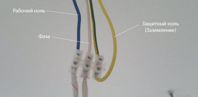
In modern cables, such methods of dyeing insulation are used:
- grounding - yellow-green;
- zero is brown;
- phase is blue.
In old houses, aluminum wiring in white insulation was used. The cable can be two-wire or three-wire. Please note that in such gaskets grounding is not provided. Depending on the number of cores, they always have 1 zero and 1-2 phases. Determining the accessory of the wire is carried out by taking measurements directly on the connected line.
In new buildings there is no such need. They have multicore cables with standard marking. In this case, grounding may not be connected. Such an engineering decision is made with a future perspective if the board of the house during its operation will ground the power supply system.
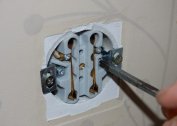
Determination of phases on the ceiling
If in a cable of a new type the search for a grounding conductor does not cause any difficulties, then with old wires it is different. If this line was installed initially, in most cases, property owners did not use it. Grounding chandeliers were simply absent at that time. A sign of a grounding contact is an insulated core bent to the side. In some cases, the owners simply cut it off to avoid confusion in the future.
After determining the land, you need to find the phase. This is done using a screwdriver indicator or tester.Upon contact with the phase, the indicator will glow, and the measuring device will show the voltage level in the network.
At the end of the measurements, it is necessary to mark the cores in any convenient way, and bend the ground wire (if its use is not planned) to bend to the side and insulate. So it will not interfere with the work and will not provoke a short circuit.
Wiring wiring
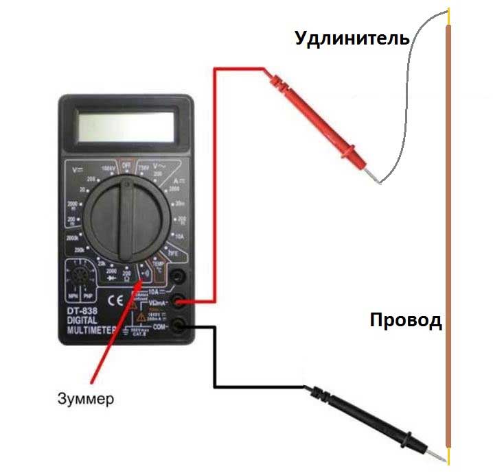
The line is drawn for several purposes. First of all, it is necessary to determine its integrity, the absence of gaps and bad contacts. If defects are found, the wiring must be changed. Secondly, the dialer allows you to determine the correct connection of wires in the switch block. In the open state, one of the terminals of the device must have a phase. If it is not, the installation was carried out incorrectly. It should not be ruled out the version of the assumption of error when switching the junction box.
When dialing the indicator, extreme care must be taken not to connect adjacent contacts with the probe. If there are errors in the assembly, this will lead to a short circuit. Measurements are taken alternately on each core. If they are connected correctly, there will be 1 zero, and the rest will be phases. The presence of voltage will be indicated by the activation of a spotlight inside the device.
More accurate, eliminating stray voltage indicators are given by the tester. Before examination, the device must be put into voltage measurement mode. After this, you need to find the channel through which current is supplied. This will be indicated by the readings on the display. Then you need to find the neutral wire. Holding the probe on it, it is necessary, alternately, switching the keys, determine the characteristics of the cores.
Wires for connecting the chandelier
 If the initial installation of the wiring or its replacement is carried out, it is advisable to use a copper cable, as regulated by GOST. Given the insignificant load on the line, enough lived with a cross section of 1-1.5 mm. If an aluminum line is laid in the ceiling, it is necessary to consider how to connect it to the copper wires of the chandelier. It is forbidden to twist them together, since an electrochemical reaction occurs between the metals, causing oxidation and subsequent heating of the contacts. This may result in fire or short circuit.
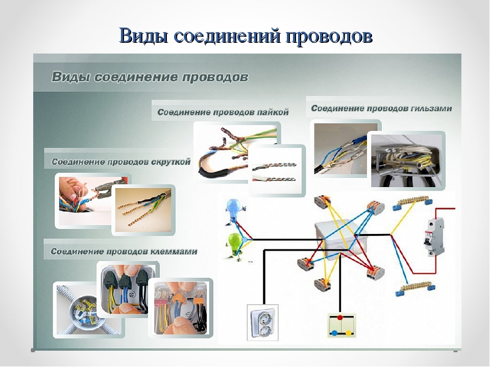
There are such options for switching wires:
- Twisting. To achieve a tight fit, pliers are used. Then the metal is wrapped with insulating tape.
- Soldering. It is the most reliable and durable way. Its minus is that it is extremely difficult and dangerous to carry out such work at height.
- Terminal block. The product provides a strong and corrosion-resistant connection of several lines on a common iron base, where the contacts are fixed with bolts. The fixture is indispensable when connecting a chandelier with 6 bulbs to a double switch. In such cases, twisting and soldering are almost impossible tasks.
In the process of switching, it is advisable to use a solid wire. It plays the role of a suspension, on which a chandelier is suspended from a hook for the period of connecting the wires. This solution will allow you to do the work yourself, without involving an assistant who also needs backup.
Connection of wires in the chandelier
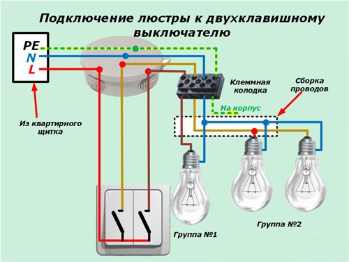 Connecting a chandelier to a double 2-lamp switch requires the use of one or two light sources. In this case, the wires with the phases are interconnected, and the neutral conductors of the device are fixed on the zero wire of the line.
When devices are connected to the network that have more horns than the number of active wires, the bulbs are combined into groups. How many will be in each is determined by practical and design necessity.There are many options, the most interesting is the connection scheme of the two-gang switch to the 1 + X chandelier, where 1 is the night or evening lighting on duty, and X is the rest of the lamps that create the main background. However, each property owner chooses the combination himself. The creation of groups is carried out by twisting channels with isolation of the same color.
Options for activating a 3-bulb chandelier on a double switch can be 1, 2 and 3 of the consumer involved. 2 and 1 active wires from the device into phases, and 3 neutral wires to zero.
When installing a product with 4 shades, the combinations can be 1 + 3 or 2 + 2. Here the algorithm is the same as with 3 shades: 2 wires per phase, 4 passive to zero.
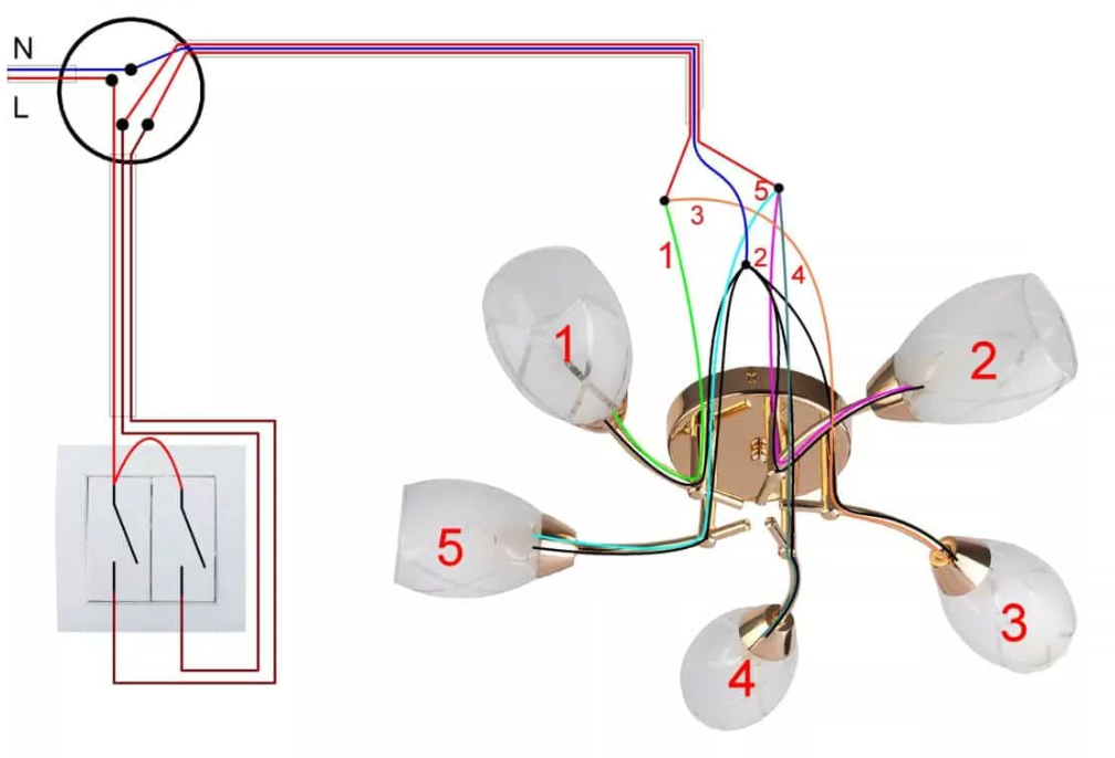
Connecting a 5-lamp chandelier to a double switch can be performed in combinations:
- 1 + 4;
- 2 + 3;
- 5.
The difference with the previous options is the composition of the groups. First, the zeros are connected by a five-arm device, then the twists are fixed on the phases in one of the selected ways. If it is necessary to use all 5 shades, active wires are connected to the right or left key.
A six-arm lamp can work according to this scheme:
- 1 + 5;
- 2 + 4;
- 3 + 3;
- 6.
Installation is carried out similarly to all previously described processes.
If you need to make night lighting, a single ceiling is equipped with a low-power lamp up to 10 watts.
Frequent connection errors
When conducting electrical work, novice masters make the following mistakes:
- ignoring the insulation of the ground line;
- twisting directly copper and aluminum conductors;
- the use of cables with insufficient or excessively high power;
- output to the zero phase switch;
- insufficiently durable twisting;
- installation on an unstable and uncomfortable base.
The key to success lies in adhering to security measures and thoughtful preparation for work.