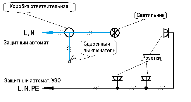
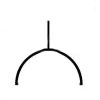
Before arranging a home electrical network, you need to make a drawing with the main components - an input line, a meter, an RCD, distribution boxes, and a lighting system. The designation of the outlet on the power supply circuit is regulated by law. The device in accordance with GOST is marked with a semicircle, from the convex side of which dashes extend like a switch.
The need for a scheme
In order to ensure high-quality and safe placement of wiring, a plan is drawn up. It has the form of a drawing with respect to scale. The document reflects the layout of the apartment, the points of placement of wiring nodes in groups, as well as circuit diagrams.
To understand the drawing, all participants in the repair and installation work, sockets and switches are indicated by graphic drawings in accordance with the all-Russian and global standards.
As graphic markers, geometric shapes are used - circles, squares, rectangles, points and lines. Their combinations reflect varieties of lighting system mechanisms and control features of these devices.
Normative base
On the territory of the Russian Federation, the designation of a group or single outlets and switches on the design drawings is subject to the following documents:
- GOST 21.614-88. Subsection “Conventional graphic images of electrical equipment and wiring” from the section on the system of design and construction documentation;
- GOST 21.210-2014. Electrical appliances, according to the norm, can be depicted in the form of standard symbols;
- IEC 60027. The standard adopted by the International Electrotechnical Commission, according to which the wiring in Russian buildings must comply with international requirements.
The regulatory documentation noted the specifics of creating conventional icons for power lines and auxiliary devices on the working scheme.
Specificity of designations in Russian GOSTs
The domestic regulatory framework, indicating which rules and methods the marking of parts of the electrical circuit is subject to, includes the following GOSTs:
- 2.755-87 - the section on conditional icons for contacts and switching connections determines the way of designating thermal relays, contactors, circuit breakers, circuit breakers. There is no graphic index for RCDs and difratomata;
- 2. 721-74 - it is indicated which sign is used for common parts and components and secondary power networks;
- 2. 709-89 - the features of graphic marking of sections of the electric circuit, special equipment, cable connection technologies and other elements are noted.
In GOST 2.702-2011, the possibility of arbitrary image of nodes and the need for decryption of markers are prescribed.
Types of electrical circuits adopted in domestic practice
According to the requirements of ESKD, the scheme is a graphic document, where the structural parts of the system and the technology of their connection are marked with special icons. According to the accepted international classification, there are more than 10. Not all are used on the territory of the Russian Federation.
Functional and structural diagrams
Structural - the simplest scheme in which the image of the circuit elements is made by squares with explanations. This technique helps to understand the features of the system. The functional drawing contains a detailed description of the nodes, their electrical connections.
Principal circuit
It is used for arranging distribution lines and control panels.On it are drawn elements without mutual arrangement. A principal drawing happens:
- single-line with power circuits - one common line is used for earth, phase and zero;
- complete with all nodes and cores of their connection - electrical communications are drawn in a detailed and element-wise form.
A complete circuit diagram is compiled on several sheets.
Assembly drawing
It contains a plan for the placement of lighting devices, sockets and switches indicating the connection method. May contain additional information needed for electrical work.
If necessary, to save space on the sheet and knowledge of labeling without signatures, a unified scheme is used. It combines the above types of drawings.
The specifics of the designation of the outlet in the diagram
Electrical accessories are classified by degree of protection, installation method, number of poles. These parameters explain the differences in the symbols in the drawing.
Symbols of sockets for outdoor / outdoor installation
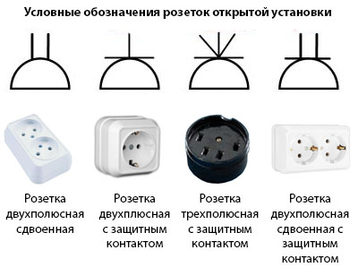
The following designations are indicated on the hardware diagram, selected for the external installation method:
- pairedness, grounding and unipolar;
- pairedness, lack of "earth" and unipolarity;
- uniqueness, one pole and presence of a contact of protection;
- power type socket that has 3 poles and protection.
A single-pole double outlet looks like a semicircle with a dash in the center. The bipolar has two lines. Bipolar models with grounding for open installation are designated as a semicircle with a horizontal line protruding on both sides and a vertical dash. Three-pole devices with “ground” - a semicircle with 5 fan dashes (1 in the center and 4 on the sides). Single devices are marked with a single line, double - with a double dash.
Three-phase switches are suitable for the three-phase network type, denoted as a semicircle with three external dashes.
Designations of sockets for flush / internal installation
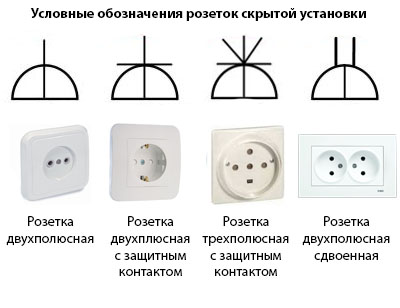
A socket intended for concealed wiring is indicated on the diagram in the form of a semicircle crossed in a vertical line.
Modifications are installed internally:
- bipolar - a semicircle with a central vertical line extending beyond the outline of the figure;
- bipolar with protective contact - a semicircle with a vertical dash pointing up and horizontal, protruding from it;
- three-pole with protective contact - a semicircle with a dash inside in the center and black lines (5 pieces on top);
- bipolar double - a semicircle with a dash in the center and two bold parallel lines (resembles a plug).
The horizontal ground line is the same for all models.
Marking of moisture-proof sockets (degree of protection of the IP44-IP55 case)
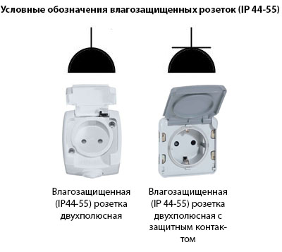 An icon in the form of a black, fully shaded semicircle is designed for moisture-resistant switching devices. The picture is deciphered as a device with a protective cover that prevents moisture from accessing the main elements. The wiring diagram in the bathroom and in the kitchen provides 2 types of sockets:
- waterproof with two poles - a black semicircle with a dash on top;
- waterproof with two poles and a protective circuit - a black semicircle with a horizontal line and a line on top.
The marking of the degree of protection in English letters IP indicates its presence. The first digit indicates the level of dust protection, the second - moisture protection.
How are the blocks from the switch and socket indicated
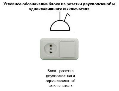 To save space under the gate and ease of layout, the lighting controllers are housed in a common housing. The circuit breaker and the socket are indicated on the diagram, depending on the number of elements:
- Block for flush mounting (1 switch + 1 socket) - a semicircle with a vertical line protruding upwards. A T-shaped diagonal line departs from its lower part.
- Block for flush mounting (1 switch + 1 socket with grounding) - a semicircle with vertical and horizontal dashes (form a cross).From the bottom of the figure there is a diagonal line in the form of the letter T;
- hidden double block of switches and a socket with grounding - a semicircle with a vertical and horizontal line in the form of a cross. From the common point to the left and to the right go diagonally T-shaped dashes;
- a unit in which there is a two-key and one-key switch, as well as a socket - a semicircle with dashes vertically and horizontally forming a cross. To the left of the common point comes a T-shaped diagonal dash. On the right is a line with a diagonal direction and two short horizontal lines that “cover” it.
Due to the complexity of the block diagrams, it is better to indicate footnotes.
Specification of circuit breakers
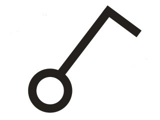
The generally accepted designation of the switch on the power supply circuit has the following form:
GOST 21.210-2014 states that for push-button models and dimmers there is no single icon. In clause 4.7. The document says that you can take arbitrary values.
Sometimes the drawings indicate an automatic switch type. Its symbol is shown in the table.
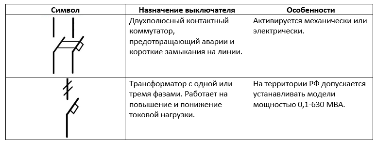
The graphic symbols that are used to designate the switch are indicated in the form of a table.
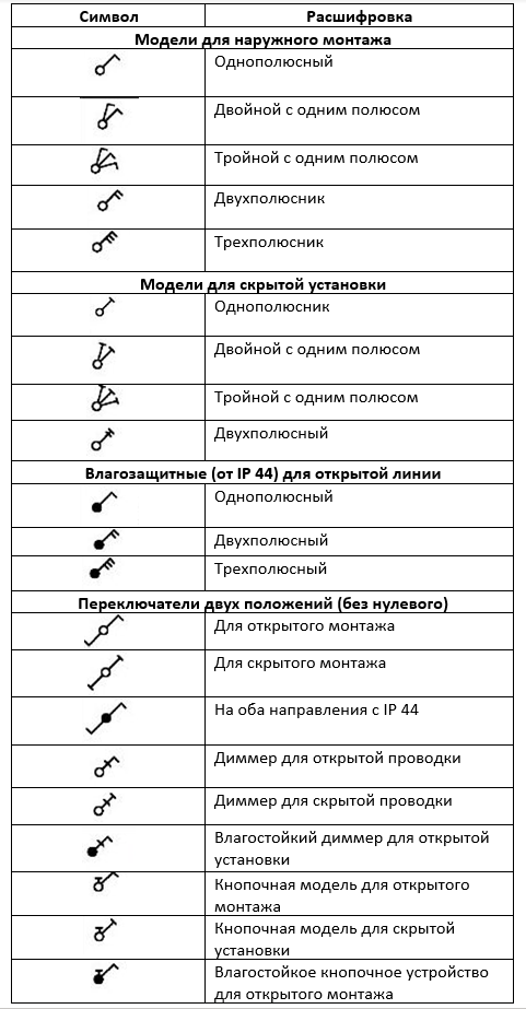
GOST 21.614-88 contains recommendations on conditional icons for switch groups:
- for open installation (protection from IP20 to IP23);
- for hidden wiring (protection from IP20 to IP23);
- moisture resistant devices (protection from IP44 to IP55);
- two-way feedthrough device with protection from IP20 to IP23;
- moisture resistant passage models with protection from IP44 to IP55.
GOST R-52565-2006 notes that the pole of one switch must close only one line.
Marking single-key and two-key models on wiring diagrams
To indicate the switch, you must specify the number of keys. For this purpose, the following symbols are used:

Three-key devices are designated as a dash with a circle and three hooks.
Symbols for other devices
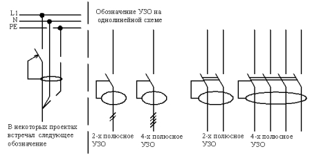
In addition to switches and sockets, the wiring diagram contains other nodes. For example, a circuit breaker, RCD, relays for monitoring voltage are indicated as an open contact.
According to GOST, a certain number of contacts connected to each other and a square on the side are used to mark the circuit breaker. The image indicates simultaneous operation and the presence of protection. At the entrance, the apartment is equipped with a bipolar machine, unipolar are used to stop the load.
Difavtomats and RCDs do not have badges regulated by GOST, therefore, the design details are shown in the drawings. RCD devices are current transformers with an executive contact relay. The differential machine has a similar assembly, but an automatic machine is added to the nodes that protects against short circuits and overload.
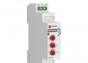
The controller relay is designed to turn off the equipment in case of exceeding the voltage rating. It is a board and contact relay. The circuit is applied to the cover of the device and transferred to the power plan.
For backlight and lighting devices, several graphic symbols are used:
- square - luminescent light source 600x600 mm;
- rectangle - fluorescent lamp 600x300 mm;
- a square with two lines - an LED light source with a size of 600x600 mm;
- a large "bow" with partially painted over black triangles - emergency lighting device 600x600 mm;
- narrow “bow” with partially filled black areas on the triangles - a device for emergency illumination 600x300;
- circle divided by an arc - a device with a high pressure bulb;
- a circle without two segments with 4 dashes ("segments") and a horizontal arrow to the right - spotlight;
- a circle divided in half - a light source with contact lamps of a luminescent type;
- a circle with narrow areas at the top and bottom - an LED lamp of any non-linear shape;
- circle - a lamp with a halogen or incandescent lamp;
- a circle divided into 6 segments - a chandelier;
- rectangle - linear fluorescent lamp;
- a rectangle with 2 dashes - a linear LED lamp;
- black bow - emergency light.
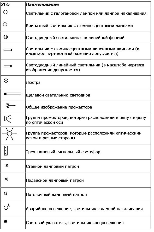
The device icon is selected depending on their appearance and purpose.
Symbols of parts of the mains do not need to know by heart. If you understand the icons and correctly drawn up the drawing, the user will always decrypt the characters or familiarize themselves with the footnotes.