There are many electrical appliances and samples of industrial equipment, characterized by an intermittent cycle of operation. They turn on for a certain time, after which it is required to remove electric voltage from them. The owner has to constantly be distracted, watching the products connected to the source. This function can be performed by modern time relays, which allow to automatically disconnect the load from the network after a fixed time period (it is called shutter speed). It can be set by the user himself, having previously calculated the necessary moment of switching off the consumer.
What is a time relay
A temporary relay is an electromechanical (electronic) device, the main purpose of which is to automatically turn off the load with some delay. Devices of this class are widely used in the electrical networks of industrial plants, allowing you to control the modes of their work without human assistance. In addition, time relays are used in everyday life, providing timely removal of 220 volts from devices connected through them. As such loads can be used:
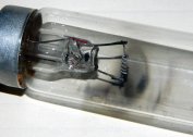
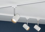
- household illuminators of any type;
- samples of climatic equipment;
- ventilation systems and other devices.
The use of modern devices with a time delay can significantly reduce energy consumption and facilitate the life of an ordinary person.
The first samples - mechanical prototypes of these devices - were developed in the middle of the XIX century. They controlled the switching on and off of the lines of the telegraph communication developing then. Since then, these products have improved significantly, their functionality has increased markedly. At the same time, the principle of operation of such devices has remained the same: after a specified period of time, the actuator is activated, after which the supply voltage is automatically removed from the load or applied to it. In industrial equipment control systems, the switching of controlled circuits is carried out according to a certain algorithm defined by programming electronic relays.
Operation algorithms, functional diagrams, conventions
In modern programmable devices, a complex algorithm of work is provided, which includes time pauses and cyclically repeated intervals. There are the following schemes for the operation of a time relay:
- simple delay of the moment of inclusion;
- after power is supplied, the load is connected, but after a time specified by the program, the voltage is removed from it;
- the same as in the previous case, but the shutdown occurs with some delay.
Another scheme involves a more complex cyclic mode of operation of the device. For his understanding, the order of switching on and off the load should be clarified. It looks like this:
- After the supply, the power is supplied for its intended purpose only after a certain period of time.
- For a predetermined interval, the line remains connected to the network.
- There is a shutdown and pause equal to its duration when power is applied.
- The load is reconnected at the same time as the first time.
- The sequence of these actions continues until the complete removal of the supply voltage.
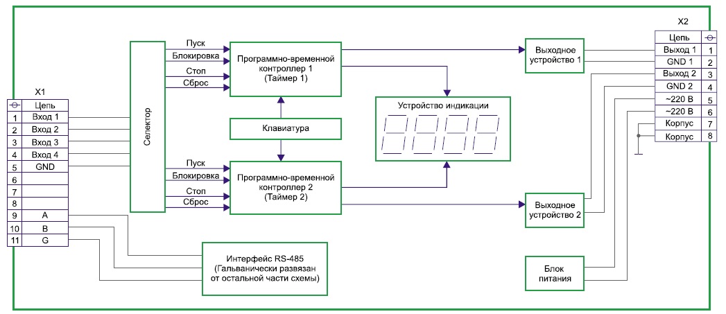
In the study of time relay triggering algorithms and features of its application, you will need to familiarize yourself with one of the most important characteristics of the device, presented in the form of a functional diagram.
Response diagrams
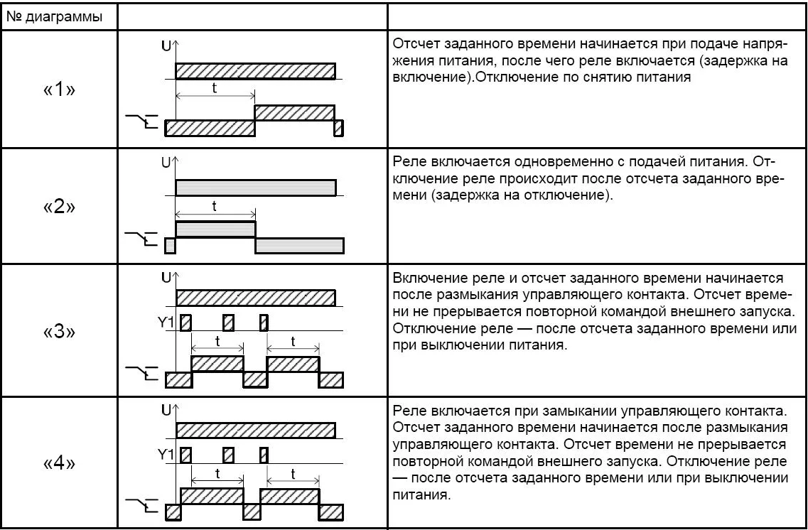
This characteristic refers to graphic diagrams describing the state of a time relay at various points in time. When you get acquainted with them, the entire process of switching is presented in a visual form.
In the diagrams, the cyclic nature of the processes observed when the devices operate according to a complex algorithm is especially clearly distinguishable. The time intervals indicated on them are usually set by the user. On the other hand, there are known devices in which the moments of disconnection and connection of the load cannot be adjusted. As a fixed parameter, they are usually indicated in the product passport. Most often, these are special purpose time-setting devices installed in protective circuits of industrial plants.
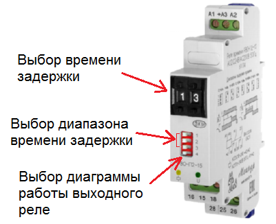
In each individual sample of the time relay, several operation algorithms are provided at once, chosen at the discretion of the user. The appearance of functional diagrams is given on the product body, where you can also get acquainted with the location of its contacts.
Designations of contacts on the diagrams

When choosing a time relay, it is important to learn to understand not only the functional response diagrams, but also the layout of its working contacts. Among them are the following types of contact groups:
- one of them in the idle position is always open;
- the other group of contacts under normal conditions is in a closed state;
- the third variety has a neutral position.
To understand the nature of the relay operation on the circuits, they are indicated by special icons in the form of semi-ovals, straight line segments and truncated parallels.
Types of Relays
According to the method of connection to the current mains, all relay devices are divided into the following classes:
- block type devices;
- switches built directly into the electronic circuit;
- modular designs.
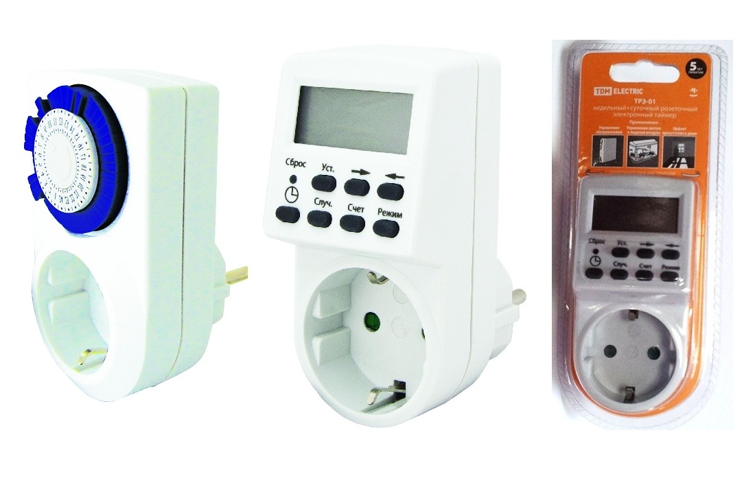
Block-type devices are made in the form of a monolithic adapter, plugged directly into an outlet. Their contacts are directly connected to the phase and zero of the switched circuit. Embedded samples do not need a third-party power source, as they work as part of complex electronic circuits.
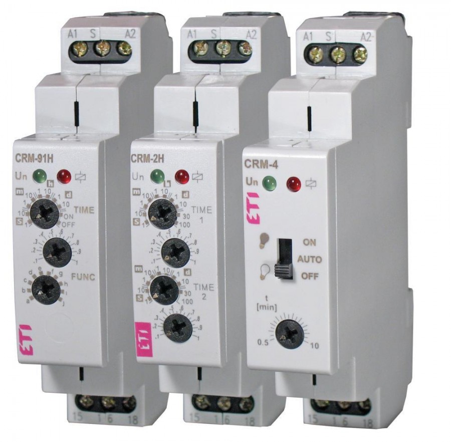
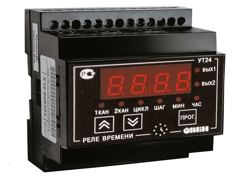
Modular timers are mounted on a DIN rail in the control cabinet and connected to the adjacent zero and phase bus. In accordance with the design features of a particular actuator, all known relay designs have the following designs:
- electromagnetic type;
- devices made on the basis of an electronic circuit;
- pneumatic and electromechanical devices similar to clockwork (the latter resemble watches in appearance).
In private practice, electronic and electromagnetic devices are widely used, due to the simplicity of their design and relatively low cost.
By the type of mechanism that provides a time delay, these devices are divided into the following classes:
- with electromagnetic deceleration;
- pneumatic (compressor);
- with a clock (anchor) retarding mechanism;
- motor systems;
- electronic mechanical analog devices.
Each of the listed samples differs from analogues in its characteristics and is used in specific conditions at the discretion of the user. Modular constructions installed on a DIN rail can be used as a temporary 220 Volt relay for lighting inside buildings.
Weekly Digital Timer
A digital weekly timer or electronic time switch is a flexible programmable device that is designed to operate within seven calendar days. With its help, it is possible to set the exact dates of the necessary switching (connections or disconnections of specific loads) in public institutions such as a school, office and similar places of collective use.
In the "advanced" samples of daily timers, it is possible to save copies of several programs with the ability to read. As storage media, various types of drives are used, allowing you to remove it using the electronic key D KEY (in the version of PLUS and SYNCHRO systems).
Setting up electronic mechanical analog relays
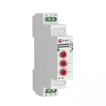
 Industrial ACS systems and some household devices are often equipped with electromechanical devices, for the normal functioning of which special adjustment is required. On their front panel there is a potentiometer handle "under the slot", rotating with a screwdriver with a thin sting. All around the circle next to it there is a marked graduation scale of the time setting.
On some models, the front panel provides LED status indication. To set the desired interval, it is enough to turn the potentiometer rod with a screwdriver to the corresponding mark with the next value in minutes or hours. Devices of this class (type NTE8, in particular) are widely used in home ventilation control schemes, heating modules, as well as in artificial lighting systems.
Instrument adjustment with digital scale
The setup of devices of this type is illustrated by the example of a timer with a digital scale of the REV Ritter brand, which is plugged into a regular power outlet. The period of action of its time delay, as a rule, is limited to one day, which is quite enough for living conditions. Instructions for setting up such a relay include the following items:
- Plug the device into a power outlet.
- Move up all the adjusting elements (segments) that are set around the circumference of the tuning disc.
- Slide down only those that correspond to the time set.
- The center disk pointer is set to the current time.
If segments located between the numbers 18 and 20 are shifted down, the desired load will turn on after the 18 hour interval and turn off after two hours. The design of such a semiautomatic device provides for the possibility of organizing up to 48 work cycles (on and off) within two calendar days.
Connection to the control circuit
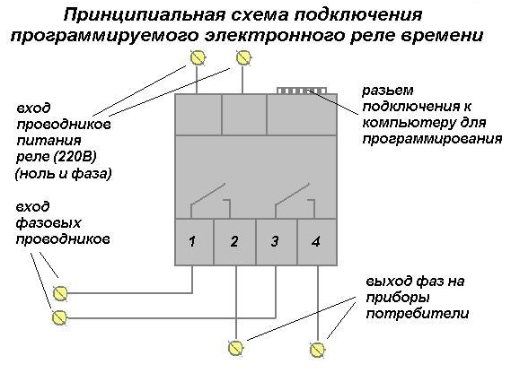 The classical scheme is used, which allows switching the multi-position load according to the time attribute (in this situation, the number of states is 2). For devices of this class, a technical passport is necessarily attached, which describes not only their design, but also the order of connections.
On some models of electronic-mechanical and digital timers, the circuit is plotted directly on the device body.
The classic version of switching is presented as the following sequence of operations:
- When connected to the mains, power is supplied directly to the device terminals.
- Through the built-in automatic machine, the phase voltage is supplied to the coil of the executive relay.
- Its contactors connect the circuit directly to the power line.
The principle of connecting most relay devices is essentially the same. When power is supplied to it, an internal circuit is triggered, due to which voltage is supplied to the load through a group of switched contacts.