In general, current strength (CT) is a value that shows how much electricity has passed through the cross section of a conductor in one second. It is believed that in the conductor it reaches a value of 1 A in the case when an amount of electricity equal to 1 coulomb passes every second through its cross section. Measure it in amperes (A). Additional units such as milliamps (1/1000 A) and microamps (1/1000000 A) are also used.
Why do I need to measure current
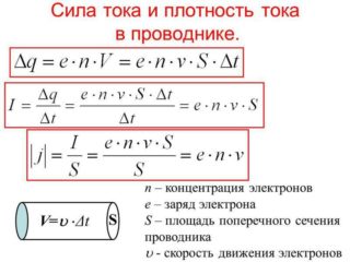 The voltage and electrical circuit resistance, which are measured in units such as volts (V) and ohms, respectively, have a significant effect on the magnitude of the current strength. In this case, an increase in voltage with a constant electrical circuit resistance causes an increase in current strength, and an increase in circuit resistance at a constant voltage value leads to its decrease. The current strength (I), voltage (U) and resistance (R) depend on each other and are related by empirical formulas:
- I = U / R
- U = I * R
- R = U / I
At the same time, it is simplistically accepted that a current of 1 A occurs in a conductor with a resistance of 1 Ω if a voltage of 1 V is applied to it.
By measuring the CT with a multimeter, you can:
- specify the actual power consumption of a particular appliance;
- find defects in the appliance if its real power does not match the value stated in the documentation;
- find out the electrical capacity of autonomous power sources (batteries, etc.);
- identify the existence of current leakage in the electrical circuits and, if necessary, localize the defective area;
- check the battery charger for compliance with the charging current set value, etc.
Such measurements are carried out using special instruments - ammeters. There are enough of them on the domestic market to satisfy the needs of all customers.
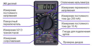
The most popular, especially at the household level, are small multifunctional (ammeter + ohmmeter + voltmeter) multimeters, with which you can measure almost all the necessary parameters of the electrical circuit.
Multimeter device
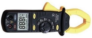
A modern multimeter (tester) is a complex electronic device. These measuring instruments differ in the principle of operation and in the way they display the results. At the same time, their device and appearance depend entirely on the manufacturer, who has the ability to equip multimeters with additional capabilities. For example, there are testers equipped with built-in conductive clamps, which allow you to measure the electrical parameters of the circuit without breaking the wires.
Classification and principle of operation
By design, multimeters can be stationary and small. In addition, based on the circuitry, they can be:
- analogue;
- digital.
Stationary multimeters operate, as a rule, from a centralized power supply network. They are precision electronic devices and are used for precision measurements in laboratory or industrial conditions. They also work as a part of information-measuring systems and specialized industrial complexes. In small-sized (pocket) testers, built-in batteries or replaceable power supplies are used to measure resistance.
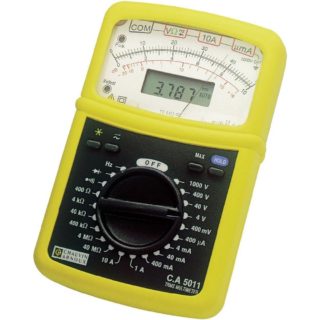
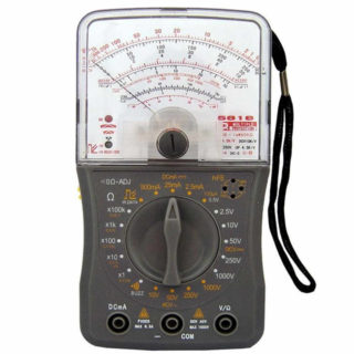
In analog multimeters, the measurement result is displayed by the deviation of the arrow on the graduated scale, and in digital ones - on the LED display or LCD screen. Original models equipped with a dial indicator and a digital screen can also be found.
The electrical circuit of analog multimeter analog multimeters is simple and represents a set of shunting precision resistors of large and small nominal value. So that with the help of such testers it was possible to measure the parameters of AC electrical circuits, rectifier diodes are introduced into the circuit. This is due to the fact that the magnetoelectric system of the dial microammeter operates only on direct current.
The electrical circuits of digital multimeters are much more complicated and contain the following components:
- operational amplifier;
- attenuator;
- analog-to-digital converter;
- high precision rectifier;
- mechanical or electronic switch.
The block diagram is the base for all digital multimeters and allows measuring the parameters of electric circuits of direct and alternating current with high accuracy.
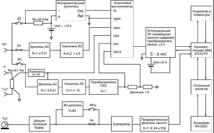
The principle of operation of analog testers is based on the fact that the measurement is preceded by the conversion of all incoming signals into a current, which is then measured. In contrast, digital multimeters pre-convert all incoming signals to voltage.
Basic principles of current measurement
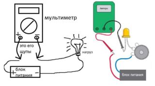
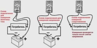
The main condition that must be met when measuring the CT in an electrical circuit is to include the tester in the wire break of this circuit, that is, to become an integral part of it during the measurement. Before measuring the current strength with a multimeter, it is equally important to correctly set on the device:
- measurement mode (direct or alternating current);
- upper limit of measurements.
Incorrectly set parameters will necessarily lead to damage to the measuring device.
When the user does not know the order of magnitude of the current strength in the circuit, it is necessary to set the maximum measurement limit. If the set range is too high, it is gradually reduced, using the tester mode switch for this.
In an electric circuit, a device for measuring current is connected in series with the load. When measuring high currents, the multimeter is connected to the circuit through a current transformer, a shunt or a magnetic amplifier. If measurements need to be carried out in electrical circuits with a voltage of more than 1 kV, use a current transformer (alternating current) or a magnetic amplifier (direct current).
Safety precautions
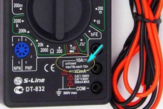
Measurements carried out in electrical circuits under a dangerous voltage of ~ 220 V require compliance with safety regulations. Safe for humans is considered a current value of not more than 0.001 A. Any, even a slight excess of it can lead to defeat of the user. Therefore, when working with electricity, you need to be extremely careful and take special care.
Working on the upper limits of the multimeter, measurements should be carried out as quickly as possible. This is due to the fact that many testers do not have protection against overheating, and with prolonged contact with high current they can simply burn out, which in turn is fraught with electrical injury. Sometimes manufacturers of multimeters warn users of such a danger, stipulating, for example, that the permissible measurement time should not exceed 10 seconds. no more than once during 15 minutes
Connecting and disconnecting the multimeter is carried out after a complete blackout of the circuit. They supply power and start measuring only after completing all work on connecting the tester.
In order to avoid electric shock, it is necessary to take measures to prevent contact of exposed live parts. It is also necessary to remember that when an open electrical circuit is opened, an electric arc can occur, which will also cause electrical injury.
Current measurement
At home, the strength of the current in electrical circuits is measured in cases where it is necessary, for example, to determine the real value of the power consumption of an electrical appliance or to compare the technical parameters of the electrical appliance included in the network with the real possibilities of electrical wiring. In this case, it is necessary to remember the danger awaiting the inexperienced owner of the multimeter when trying to conduct such measurements in a power outlet. As a rule, this leads to a complete failure of the tester, and in some cases to electric shock to the user.
There is no current in the electrical outlet. On its contacts there is only voltage between phase and "zero". The current in the mains appears only after the appliance is connected to the outlet.
If the probes of the multimeter included in the current measurement mode are inserted into the outlet, a short circuit will occur in the network and the measuring device will fail. Well, if it is equipped with a fusible insert, which simply burns and disconnects the tester from the network. If the design of the device does not provide such a fuse, due to overheating, the multimeter may ignite or even “explode”.
CT measurement in an electrical circuit connected to a power source
In order to measure the current strength in the circuit of a connected electrical appliance, the multimeter must be connected to the gap of one of the power wires, as shown in the diagram.
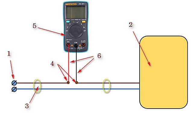
Here:
- 1 - AC power outlet or contacts of an autonomous power source;
- 2 - electrical appliance;
- 3 - wires (cable) power supply of the appliance;
- 4 - the place of breaking the electrical circuit and connecting the probes of the multimeter;
- 5 - tester included in the mode of measuring alternating current;
- 6 - test leads from the delivery kit of the multimeter.
To connect a multimeter to a circuit break, it is necessary to cut one of its conductors and strip the insulation at the cut ends.
Current measurement is carried out in the following sequence:
- The multimeter selector knob sets the required measurement mode, taking into account the type of current (alternating or constant).
- The same pen sets the upper limit of the CT measurement. In this case, it is recommended to initially choose a measurement limit that exceeds the expected value of the measured parameter.
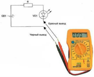
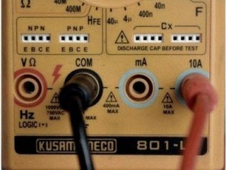
- Insert the test leads into the corresponding jacks on the multimeter.
- Connect the tester probes to the stripped ends of the wire and make sure the contact is reliable.
- Turn on the power to the instrument and record the multimeter. If necessary, you can change the upper limit of measurements and re-record the result.
- Disconnect power and disconnect the test leads from the ends of the conductor.
- Connect the cut wire and carefully insulate this place.
When making measurements in DC circuits, it is necessary to observe the polarity of the test leads.
If you need to measure the current strength without violating the integrity of the circuit, the best option would be to use a multimeter equipped with built-in current clamps.
Sometimes the need for measuring the current strength in an AC circuit can arise at a time when there is no multimeter with such a function at hand. However, radio amateurs found a way out of the situation, using testers working only with direct current to measure the current strength in alternating current circuits.It is enough to supplement the electric circuit with a diode bridge by turning on a multimeter that measures the parameters of DC circuits according to the following scheme:
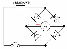
A similar result can be obtained if a special calibrated shunt with a known resistance is included in the circuit. In this case, the shunt is selected so that its rated voltage coincides with the rated voltage of the measuring device.
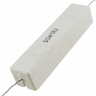
Then, in parallel with the contacts of the shunt, connect a multimeter with the set voltage measurement mode (voltmeter) and measure the voltage drop across the shunted section of the mains. How to measure voltage with a multimeter is indicated in the instructions for its use.
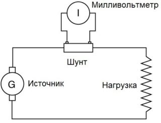
In this case, the multimeter performs the function of a voltmeter, however, the magnitude of the measured voltage will be directly proportional to the current strength. Knowing the resistance of a precision shunt, using the formula I = U / R, you can easily calculate the magnitude of the current in the circuit. If we take a calibrated shunt having a resistance of 1 Ohm, its nominal value can be determined on the scale of the voltmeter (I = U / 1 = U).
At home, such a low-impedance shunt (R = 1 Ohm) is easiest to make yourself, for example, by winding a small piece of thin nichrome wire (cross section 0.123 mm, resistivity 7.94 Ohm / m, diameter 0.4 mm), length 126 mm, on a strip of fiberglass.
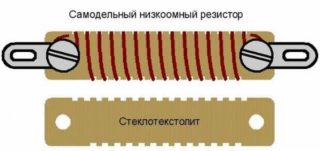
By installing a homemade resistor in an open circuit and connecting a multimeter to its contacts, you can measure the voltage on the shunted portion of the circuit. Its nominal value will correspond to the strength of the current flowing through the resistor: I = U / 1 = U.
